Table of Contents
Advertisement
Quick Links
INSTRUCTION MANUAL
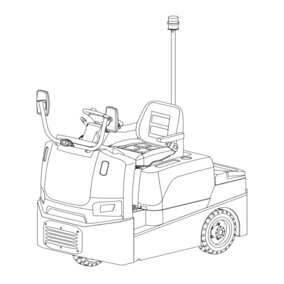
Sit-on Tow Tractor
T30Q/T60Q
WARNING
Do not operate the tow tractor before reading
and understanding the instructions of this
manual.
NOTE:
Please
parameters of your truck in this manual
as well as on the ID-plate.
Keep this manual for future reference.
check
product
type
and
Version 11/2022
T30Q/T60Q-SMS-002-EN
xyz
Advertisement
Table of Contents

Summary of Contents for Noblelift T30Q
- Page 1 INSTRUCTION MANUAL Sit-on Tow Tractor T30Q/T60Q WARNING Do not operate the tow tractor before reading and understanding the instructions of this manual. NOTE: Please check product type parameters of your truck in this manual as well as on the ID-plate.
- Page 3 FOREWORD Before operating the tow tractor, please read this instruction manual carefully and understand the usage of the truck completely, improper operation will cause danger. All instructions in this manual should be seriously followed, otherwise warranty will be invalid by default, and our company shall not be liable for any losses arising therefrom.
-
Page 5: Table Of Contents
TABLE OF CONTENTS 1. CORRECT USE AND APPLICATION ....................6 a. General ............................... 6 b. Correct application ..........................6 c. Approved application conditions ......................6 d. Proprietor responsibilities ........................6 e. Adding attachments and/or optional equipment ................. 7 2. Truck Description ............................ 8 a. - Page 6 Electrical diagram ..........................66 a.1 T30Q Electrical diagram (QT controller) ..................66 a.2 T30Q Electrical diagram for (QT controller) with pin-code lock ..........67 a.3 T30QElectrical diagram for (Curtis controller) ................68 a.4 T30Q Electrical diagram for (Curtis controller) with pin-code lock ..........69...
- Page 7 a.5 T60Q Electrical diagram (QT controller) ..................70 a.6 T60Q Electrical diagram for (QT controller) with pin-code lock ..........71 a.7 T60QElectrical diagram for (Curtis controller) ................72 a.8 T60Q Electrical diagram for (Curtis controller) with pin-code lock ..........73 8.
-
Page 8: Correct Use And Application
1. CORRECT USE AND APPLICATION a. General The tow tractor described in this manual is a equipment suitable for towing trailer loads. The tow tractor must be used, operated and serviced in accordance with the present operating instructions. Any other type of application is considered improper use and may result in injuries to personnel and damage to the tow tractor or other property. -
Page 9: Adding Attachments And/Or Optional Equipment
prevention regulations, safety regulations and operating, servicing and repair guidelines must be followed. The tractor may only be operated by persons who have received the relevant special training. The operating company must ensure that all operators have read and understood these operating instructions. -
Page 10: Truck Description
2. Truck Description a. Application This tow tractor is a rear-drive electrically controlled industrial truck and a load tractor for traction. This tow tractor is intended for indoor or outdoor use. Generally, it is not necessary to replace the battery, but if it is used intensively, the battery should be replaced (see "Battery - Servicing, Recharging, Replacement"... -
Page 11: Assembly Overview
b. Assembly Overview Item Description Item Description ● Battery panel latch ○ Aviation connector (trailer running socket) ○ Warning lamp ● Storage table (load capacity 25kg) Seat ● ○ Pin-code lock (with seat switch and safety belt) ○ Arm rest ●... -
Page 12: Functional Description
b.1 Functional Description Overview The chassis is of steel structure, and the steps on both sides of the tractor are low. The battery panel can be flipped over, tilt it back when changing and servicing the batteries. The trailer coupling has 3 layers and comes with a trailer connector. -
Page 13: Technical Data
c. Technical data The technical data given below are in accordance with the VDI2198 standard. Our company reserves the right to make technical changes and supplements. - Page 14 Main technical data for standard version Type sheet for industrial truck acc. to VDI 2198 Manufacturer’s type designation T30Q T60Q Drive: electric (battery type, Electric Electric mains, ...), diesel, petrol, fuel gas Operator type: hand, pedestrian, Seated Seated standing, seated, order-picker...
-
Page 15: Description Of Identification Plate, Safety And Warning Labels
d. Description of identification plate, safety and warning labels Keep the safety and warning labels and the identification plate intact and legible. Replace if necessary. Item Description Identification plate Notice label: “Observe the instructions manual” Attachment points for loading by crane... -
Page 16: Identification Plate
d.1 Identification plate Type XXXX Serial Number XXXX Manufacture date XXXX Rated drawbar pull XXX N Max. drawbar pull XXX N XX V XXX kW System voltage Rated power Service weight (without battery) XXX kg XX/XX kg Battery mass, min./max. Rated capacity XXX kg XXXXXXXXX... -
Page 17: Transport And Commissioning
3. Transport and Commissioning a. Lifting by crane Incorrect crane loading and unloading procedures can result in accidents. Improper use or use of unsuitable lifting equipment can cause the truck to crash when being loaded by crane. ● Prevent the truck from hitting other objects during lifting, and avoid uncontrolled movements. If necessary, secure the truck with guide ropes. -
Page 18: Transport
b. Transport The truck must be securely fastened when transported on a lorry or a trailer. The lorry or trailer must have fixing plate. Tighten the lashing strap (3) for fixing the tractor and fix it on the fixing plate. Loading and unloading should be carried out by specially trained staff. -
Page 19: Move The Tractor Without The Tractor's Own Drive System
If the tractor has been parked for a long period, the wheel surfaces may tend to flatten. Once the tractor has covered a certain distance, the flattening will disappear automatically. d. Move the tractor without the tractor's own drive system If the tractor breaks down and affects normal driving but must be moved, follow the steps below: ●... -
Page 20: Battery - Servicing, Recharging, Replacement
● There must be an authorized driver sitting in the driving position of the towed truck to control the direction of travel of the towed truck. Step speed must be used when towing! 4. Battery - Servicing, Recharging, Replacement a. Safety regulations for handling of lead-acid batteries Before working on the battery, park the towing tractor properly (see Chapter 5). -
Page 21: Battery Overview
● Follow the relevant legislation and regulations. The use of unsuitable batteries can be hazardous The weight and dimensions of the battery have a considerable effect on the operational stability of the tow tractor. The use of unsuitable batteries must be approved by our company. The mass of battery is indicated on the identification plate. -
Page 22: Battery Types
Battery Battery connector Battery connector holder Charging cable of battery charging station c. Battery types Tractor model Battery type 48V 3PzS 240 T30Q 48V 3PzS 270 48V 3PzS 300 T30Q 48V 3PzS 320 T60Q 48V 3PzS 360 48V 3PzS 400 When replacing or installing the battery, pay attention to the fixed position of the battery in the battery box of the tractor. -
Page 23: Battery Removal And Installation
● The safety regulations of the battery and charging station manufacturers must be strictly observed. Procedures to charge the battery ● Unlock the battery panel latch (1), and open the battery panel (2) until it is supported by the gas spring sheath. - Page 24 ● Park the tractor according to instructions (refer to Chapter 5). ● Carefully lift the battery (5) and place it in the tractor by using the lifting equipment. ● Fix the battery, lock the battery fixture (3). ● Connect the battery connector (6) and the battery connector holder (7). ●...
-
Page 25: Truck Operation
5. Truck Operation a. Safety regulations for the operation of the tow tractor Driver authorization: The tractor may only be used by trained personnel, who have demonstrated to the proprietor or his representative that they can drive and handle loads and have been authorized to operate the tractor by the proprietor or his representative. -
Page 26: Controls And Operations
b. Controls and operations Item Description Function Steering wheel Steer the tractor. Horn button Activate an audible warning signal. Travel switch Control the travel direction (forward/ backward). Switch on and off the control current. Ensures that the tractor will not Key switch start accidentally after removing the key. -
Page 27: Display Unit
c. Display unit LDB80S04 can display the battery charge, truck speed, height, steering angle, operating hours, low battery alarm, and monitored controller working parameters on its screen. Description of key functions of the panel (as shown above): Item Description Function Fast speed mode/ current parameter +1 DOWN Slow speed mode/ current parameter -1... -
Page 28: Battery Indicator
when scheduled maintenance is required. The original SVC value is 999h, when the SVC value is reduced to 0h, it will not change and the service symbol will be always on. After carry out the truck maintenance, press “QUIT” key to reset the service timer. Zero the hour meter: Disconnect the KSI switch and the display enters standby mode, the screen backlight is off and only the hour meter is displayed. -
Page 29: Key Functions Of Curtis 3401T-5002 Display (○)
c.4 Key functions of Curtis 3401T-5002 display (○) F1: Enters/exits the 3401T-5002 Operation Menu Screen; F1 key specifies the number "1" in the Password Screen; F2: Enters/exits the 3401T-5002 Display Menu Screen; F2 key specifies the number "2" in the Password Screen;... -
Page 30: Getting On And Off The Tractor
● Inspect the trailer coupling for visible damage. ● Check the drive wheel and load wheels for damage and freedom of movement. Safety functions The operator must ensure that the traveling speed matches the actual conditions of the road, working area and loading/ unloading requirements! Before driving the tractor, make sure all moveable covers/ panels of the tractor are securely locked. -
Page 31: Preparing The Tractor For Operation
Original spare parts must be used during assembly and maintenance. Damaged or malfunctioning seat belt must be replaced by an authorized dealer or manufacturer’s branch. Measures taken in a dangerous situation When the tractor is in risk of tipping over. It is strictly forbidden to unfasten the seat belt and jump out of the tractor to escape. -
Page 32: Parking The Tractor Securely
d.6 Parking the tractor securely Make sure that the tractor is parked securely before leaving. ● The tractor travels on a level surface. ● Turn the steering wheel to the straight-ahead position. ● Turn the key switch (4) to "0" position. ●... -
Page 33: Emergency Stop, Traveling, Steering, Braking
carefully before transporting. Use suitable precautions to prevent the loads from tipping or falling down (e.g. fixing rings). Malfunction: If the electromagnetic field exceeds the permissible limit value during traveling, it may cause uncontrolled movement of the tractor. Immediately apply the service brake and press the emergency switch to stop the tractor and activate the parking brake. -
Page 34: Activating The Lights
Braking The braking performance of a tractor depends to a large extent on the conditions of the road surface. The operator must take this into account when driving the tractor. Take extra care when braking to avoid the load from slipping. When towing load, it should be noted that the braking distance will be extended. -
Page 35: Travel With Trailer
Attaching the trailer Pull out the bolt pin (10) from the trailer coupling. Attach the trailer tow eye to the trailer coupling. Put the bolt pin (10) through the hole of the trailer coupling from the upper. Uncoupling the trailer Check and confirm that the trailer has not moved. -
Page 36: Side Controls Operation
Driving with a trailer attached Drive slowly until the trailer coupling is tightened. Be careful when accelerating. Parking with a trailer attached When the trailer slows down or stops during towing operation, reduce the speed of tractor gradually. Pay attention to the safety brake. e.6 Side controls operation There is a risk of pinching from the tow tractor. -
Page 37: Operating Instructions For Pin-Code Lock (○)
f. Operating instructions for pin-code lock (○) f.1 Description of the pin-code lock Access code ignition switch (hereinafter referred to as "pin-code lock"), the truck will not be allowed to start until the authorized access code is entered. The main function of the pin-code lock is to prevent unauthorized access. -
Page 38: Trouble Shooting
g. Trouble shooting This chapter is intended to help users identify and troubleshoot simple faults or problems caused by operating errors. Please check step by step in the sequence of operations in the table below to determine the specific cause of the malfunctions. TROUBLE CAUSE REMEDY... - Page 39 In speed mode, the speed command Controller failure, contact manufacturer. exceeds the maximum motor rotation speed. In torque mode, the torque command Controller failure, contact manufacturer. exceeds the maximum motor torque. No speed feedback detected. Approaches: Check the wiring between the speed sensor and the controller;...
-
Page 40: Fault Codes Of Curtis 3401T - 5002 Display Unit (○)
(P91, P101). Check whether the main contactor is damaged Main contactor contacts fused and replace the main contactor. Motor encoder short circuit; or other 5V external 5V output failure device short circuit; or it’s controller failure, contact the manufacturer. The controller CAN network ID setting is MACID detection failed repeated, reset it. - Page 41 1 = Controller Over Current 2. Motor encoder signal is interfered. Phase U 3. Motor parameters are mistuned. 2 = Controller Over Current 4. Controller defective. Phase W 3 = Controller Over Current Phase V 4 = Irms > 135 % Current Limit 1.
- Page 42 current. 3. Battery disconnected while regen braking. 4. See Programmer\ System Monitor Menu\ Controller\ Capacitor Voltage. 1. Battery-voltage applied to KSI (pin 1) exceeds the Severe Overvoltage limit. Severe KSI Overvoltage 2. See Programmer\ System Monitor Menu\ Controller\ Key switch Voltage. 1.
- Page 43 temperature. 5. See Programmer\ System Monitor Menu\ Controller\ Controller Temperature. Clear: Bring heatsink temperature below 85°C. Cycle KSI or interlock switch, or replace the controller. 1. Batteries need recharging. Controller is performance limited at this voltage. 2. Battery parameters are misadjusted. 3.
- Page 44 Programmer\ Motor Setup\ Temperature Sensor. 1. Motor thermistor is not connected properly. 2. Sensor polarity (between Pin 8 and Pin 18) is incorrect. Motor Temp Sensor motor temperature sensor parameters are misadjusted. 4. See Programmer\ System Monitor Menu\ AC Motor\ Temperature. MAIN DRIVER Fault Type(s): 1 = Driver short circuit...
- Page 45 1 = Main did not close when commanded. 2. Main contactor tips are defective (oxidized, 2 = Main disconnected during operation. burned, or not making good contact). 3. An external load on the capacitor bank (B+ connection terminal) is preventing the capacitor bank from charging.
- Page 46 Fault Type(s): (>25%) 1 = Lifting only Parameter setting error: 2 = Lowering only 1. Hydraulic suppression type 3 = Lifting and lowering 2. HPD/SRO judgment time 3. Pump throttle hardware fault While the Interlock was On, a safetyˇba sed Parameter Change parameter was changed.
- Page 47 OS General Clear: Reset Controller. 1. The time between CAN PDO messages received exceeded the PDO Timeout Period as CAN PDO Timeout defined by the Event Timer parameter. 2. Adjust PDO Settings. See Programmer/ Application Setup/ CAN Interface/ PDO Setups. 1.
- Page 48 92 PMAC Motor not accelerating. Low acceleration 94-97 PMAC lag compensation out of range 99 PMAC Motor rotating when matching starts 102 PMAC motor temp sensor fault 103 PMAC motor temp hot cutback 104 PMAC controller temp cutback 106 PMAC Undervoltage cutback 107 PMAC overvoltage cutback 1.
- Page 49 Fault type: motor technology in use. 1. Dual drive enabled in torque mode. 2. Dual drive is enabled in torque mode. 2. SPMSM motor feedback selects the 3. Dual drive enabled on only one controller. encoder. 3. AC induction motor feedback selects sine cosine.
- Page 50 Fault Type(s): 2. Dirty connector pins at controller or contactor 1 = Driver short circuit coil. 2 = Driver over-current 3. Bad connector crimps or faulty wiring. 3 = Driver open/ short circuit (voltage 4. Driver overcurrent, as set by the Driver 3 measured high, should be low) Overcurrent parameter.
- Page 51 checks are enabled. Driver 7 Fault Fault Type(s): 1 = Driver short circuit 1. Open or short on driver load. 2 = Driver over-current 2. Dirty connector pins at controller or contactor 3 = Driver open/ short circuit (voltage coil. measured high, should be low) 3.
- Page 52 2 = Below Low limit. setting of Analog 3 Low. 3. See Programmer/ Controller Setup/ Analog Inputs/ Analog 3. 4. See Programmer/ Controller Setup/ Analog Inputs/ Configure/ Analog 3 Low/ Analog 3 High. 1. Analog 4 input voltage is above the parameter setting of Analog 4 High.
- Page 53 Fault Type(s): setting of Analog 9 High. 1 = Above High limit. 2. Analog 9 input voltage is below the parameter 2 = Below Low limit. setting of Analog 9 Low. 3. See Programmer/ Controller Setup/ Analog Inputs/ Analog 9. 4.
- Page 54 Fault Type(s): Clear: Resolve battery or battery cell issue. 1 = Battery Current Cutback. 2 = Low Cell Cutback. 3 = High Cell Cutback. Reset the controller by restoring the voltage to PWM Input 10 Out of Range the allowable range 1.
- Page 55 the (PWM_Input_29_High_Frequency) +(PWM_Input_29_Frequency_Fault_Tolera nce). 4 = The measured duty cycle is below set limits, (PWM_Input_29_Low_Duty_Cycle) –(PWM_Input_29_Duty_Cycle_Fault_Tolera nce). 5 = The measured duty cycle is above set limits, (PWM_Input_29_High_Duty_Cycle) +(PWM_Input_29_Duty_Cycle_Fault_Tolera nce). Primary State Error Fault Type(s): These are internal issues either occurring during startup, parameter initialization, secondary micro update or other runtime issues.
- Page 56 0 = U phase. greater than allowed. 1 = V phase. Clear: Reset Controller. 2 = W phase. (device profile, .cdev file) incompatible with the controller. Hardware Compatibility The loaded software (.cdev) is not compatible with the controller hardware. The associated fault diagnostic with...
-
Page 57: Truck Maintenance
6. TRUCK MAINTENANCE a. Operational safety and environmental protection The inspections and maintenance tasks listed in chapter "Maintenance checklist” must be performed according to the defined service intervals. Risk of accidents and component damage Any modification to the truck, in particular the safety mechanisms, is prohibited. Never change the working speed of the tractor. -
Page 58: Cleaning
b.2 Cleaning Fire hazard Do not use flammable liquids to clean the tractor. Always disconnect the battery (by removing the battery connector) before starting cleaning work. Carry out all necessary safety measures to prevent sparking before cleaning (e.g. by short-circuiting). Risk of electrical system damage Cleaning the electronic components with water can damage the electrical system. -
Page 59: Tractor Wheels
Welding operation Before the welding operation, the electrical and electronic components of the tow tractor must be removed to prevent accidental damage to these components during operation. Set value When repairing and replacing hydraulic parts, electrical and electronic components, the specified parameters related to the tractor must be observed. - Page 60 Check the brake fluid level, refill if necessary. Change the brake fluid every 3000h, or every 2 years, and vent if necessary. Check for tightness of connectors and wires. Check brake pad for wear. Check the warning and safety devices. ...
-
Page 61: Liquid Dielectrics
Lubricate the marked points according to the maintenance checklist. (1) Sprockets and chains: apply CRC Lithium General Purpose Grease. (2) Gear oil: AFT DEXRONⅡ, T30Q oil volume ≥ 1.5L; T60Q oil volume ≥ 2.5L. 2 ◆ --- Gear oil filling port... -
Page 62: Maintenance Instructions
e. Maintenance instructions e.1 Preparations for completing maintenance operations In order to avoid accidents during maintenance, please take all necessary safety measures. The following must be done carefully: ● Park the tractor securely as required (see "Operation" in the previous chapter). ●... -
Page 63: Tighten The Wheel Hub Nuts And Bolts
Risk of accident when working under load-carrying parts, battery cover and towing tractor ● When working under the lifted load-carrying parts or tractor, effective measures must be taken to prevent accidents (e.g. falling, tipping, or sliding). ● When lifting the tractor, instructions listed in the previous chapter "Transportation and Operation" must be followed. -
Page 64: Refill With Distilled Water
● Lift off the rubber pedal pad. ● Check the brake fluid level. Brake fluid level shall be in the middle of the minimum and maximum marks, and be filled if necessary. Fill brake fluid ● Unscrew the cap (3) from the brake fluid container. ●... -
Page 65: Check Electrical Fuses
e.5 Check electrical fuses Open the rear panel, the fuses are located as shown in the figure below. Fuse Curtis FU 1 FU 2 250A 300A FU 3 e.6 Servicing the seat belt Pull out the seat belt completely and check the wear of the fiber surface. Check the function of the belt buckle and whether the seat belt retractor can properly tighten the seat belt. -
Page 66: Precautions Before Storage
f.1 Precautions before storage ● Completely clean the tractor. ● Check the brakes. ● Apply a thin layer of lubricating oil or grease on all mechanical parts without coating treatment. ● Lubricate the tractor according to the lubrication diagram (see "Maintenance" in Chapter 6). ●... -
Page 67: Scrap And Disposal
caused by improper use. The inspector must carefully record the inspection process and related data. The inspection results must be retained at least until the next inspection operation. The truck user must take necessary measures to solve the discovered problems in time. On the tractor that has been inspected, the inspection label will be affixed as an identification mark. -
Page 68: Wiring/ Circuit Diagram
7. WIRING/ CIRCUIT DIAGRAM a. Electrical diagram a.1 T30Q Electrical diagram (QT controller) Description of electrical diagram Code Item Code Item Battery Jog switch Emergency switch Combined switches Traction controller Horn switch Contactor Electromagnetic brake Fuse Brake relay Fuse Reversing buzzer... -
Page 69: T30Q Electrical Diagram For (Qt Controller) With Pin-Code Lock
T30Q Electrical diagram for (QT controller) with pin-code lock Description of electrical diagram Code Item Code Item Battery Jog switch Emergency switch Combined switches Traction controller Horn switch Contactor Electromagnetic brake Fuse Brake relay Fuse Reversing buzzer Fuse Horn... -
Page 70: T30Qelectrical Diagram For (Curtis Controller)
a.3 T30QElectrical diagram for (Curtis controller) Description of electrical diagram Code Item Code Item Battery Jog switch Emergency switch Combined switches Traction controller Horn switch Contactor Electromagnetic brake Fuse Brake relay Fuse Reversing buzzer Fuse Horn Flasher HL1, HL7 Right turn signal Accelerator HL2, HL5 Brake light... -
Page 71: T30Q Electrical Diagram For (Curtis Controller) With Pin-Code Lock
T30Q Electrical diagram for (Curtis controller) with pin-code lock Description of electrical diagram Code Item Code Item Battery Jog switch Emergency switch Combined switches Traction controller Horn switch Contactor Electromagnetic brake Fuse Brake relay Fuse Reversing buzzer Fuse Horn... -
Page 72: T60Q Electrical Diagram (Qt Controller)
a.5 T60Q Electrical diagram (QT controller) Description of electrical diagram Code Item Code Item Battery Jog switch Emergency switch Combined switches Traction controller Horn switch Contactor Electromagnetic brake Fuse Brake relay Fuse Reversing buzzer Fuse Horn Flasher HL1, HL7 Right turn signal Accelerator HL2, HL5 Brake light... -
Page 73: T60Q Electrical Diagram For (Qt Controller) With Pin-Code Lock
a.6 T60Q Electrical diagram for (QT controller) with pin-code lock Description of electrical diagram Code Item Code Item Battery Jog switch Emergency switch Combined switches Traction controller Horn switch Contactor Electromagnetic brake Fuse Brake relay Fuse Reversing buzzer Fuse Horn Flasher HL1, HL7 Right turn signal... -
Page 74: T60Qelectrical Diagram For (Curtis Controller)
a.7 T60QElectrical diagram for (Curtis controller) Description of electrical diagram Code Item Code Item Battery Jog switch Emergency switch Combined switches Traction controller Horn switch Contactor Electromagnetic brake Fuse Brake relay Fuse Reversing buzzer Fuse Horn Flasher HL1, HL7 Right turn signal Accelerator HL2, HL5 Brake light... -
Page 75: T60Q Electrical Diagram For (Curtis Controller) With Pin-Code Lock
a.8 T60Q Electrical diagram for (Curtis controller) with pin-code lock Description of electrical diagram Code Item Code Item Battery Jog switch Emergency switch Combined switches Traction controller Horn switch Contactor Electromagnetic brake Fuse Brake relay Fuse Reversing buzzer Fuse Horn Flasher HL1, HL7 Right turn signal... -
Page 76: Specialized Stipulations For Us- American Market
8. SPECIALIZED STIPULATIONS FOR US- AMERICAN MARKET a. Foreword/ Compliance Operating this truck requires knowledge which can be acquired from this instructions manual. This manual must be kept available throughout the entire period of use of this tractor. IT IS LAW; YOU MUST BE TRAINED AND CERTIFIED TO OPERATE THIS TRUCK! READ AND OBEY ALL WARNINGS AND INSTRUCTIONS IN THIS MANUAL AND ON THE TRUCK! Only properly trained operators are allowed to operate a powered industrial truck. -
Page 77: Technical Data For Us Market
Technical data for US market Main technical data for standard version (US market) Type sheet for industrial truck Manufacturer’s type designation T30Q T60Q Drive: electric (battery type, mains, ...), Electric (48V Electric (48V battery) battery) diesel, petrol, fuel gas... - Page 78 CE-DD-002 9. DECLARATION OF CONFORMITY (valid, if sold within EU) [GB] CE Declaration of Conformity The signatory hereby declares that the specified machine conforms to the EU Directive 2006/42/EC (Machine Directive) and 2014/30/EU (Electro-Magnetic Compatibility, EMC) including their amendments as translated into national legislation of the member countries. The signatory is individually authorized to compile the technical documents.
- Page 79 Ar zemāk redzamajiem parakstiem tiek apliecināts, kanorādīts mašīna atbilstEiropas Savienības normatīvām 2006/42/EG (Mašīnu normatīvas) un 2014/30/EU (Elektromagnētiskā atbilstība – EMV), ieskaitot to izmaiņas, kā arī atbilstošos tiesiskos rīkojumus normatīvu pielāgošanai nacionālajai likumdošanai. Parakstu īpašnieki ir atsevišķi pilnvaroti sastādīt tehniskās dokumentācijas. [N] EU-KONFORMITETSERKLÆRING Undertegnede bekrefter hermed at de enkelte betegnede maskin med kraftdrift tilsvarer de europeiske retningslinjene 2006/42/EC (maskinretningslinje) og 2014/30/EU (elektromagnetisk fordraglighet - EMV) inklusiv disses endringer og den tilsvarende rettsforordning...