Table of Contents
Advertisement
Available languages
Available languages
Quick Links
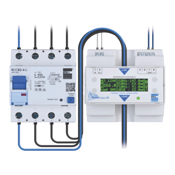
Ableitstromkompensation in Netzen mit Servo-Antrieben
und Frequenzumrichtern
Leakage current compensation in networks with servo drives
and frequency inverters
Kompensation betriebs-
bedingter Ableitströme
bis zu 500 mA (RMS)!
Erhöht die Betriebs-
sicherheit von Anlagen
Einsatz von FI-Schutz-
schalter mit einem Limit
von 30 mA oder höher
nach DIN VDE 0100-530
möglich
Compensation of
operational leakage
currents up to
500 mA (RMS)!
Increases the
operational safety of
installations
Use of RCDs with a limit
of 30 mA or higher
according to DIN VDE
0100-530 possible
Original
Betriebsanleitung
Instruction manual
Advertisement
Chapters
Table of Contents

Summary of Contents for EPA LEAKCOMP HP
- Page 1 Ableitstromkompensation in Netzen mit Servo-Antrieben und Frequenzumrichtern Leakage current compensation in networks with servo drives and frequency inverters Original Betriebsanleitung Instruction manual Kompensation betriebs- bedingter Ableitströme bis zu 500 mA (RMS)! Erhöht die Betriebs- sicherheit von Anlagen Einsatz von FI-Schutz- schalter mit einem Limit von 30 mA oder höher nach DIN VDE 0100-530...
- Page 3 EPA entschieden haben! Wenn Sie technische Fragen haben, rufen Sie uns gerne an: Tel.: +49 (0)6181 – 9704 – 0 Aktuelle Infos zum Produkt finden Sie auf www.leakcomp.de und www.epa.de. Alles kurz und knapp auch im Video unter lchp-video.epa.de. _____________________________________________________________________________ Wir danken unserem wissenschaftlichen Beirat der Hochschule Emden-Leer für die Unterstützung:...
-
Page 4: Table Of Contents
Wichtige grundlegende Informationen Inhalt Wichtige grundlegende Informationen ................4 Impressum ....................... 4 Zielgruppe ........................ 5 Allgemeine Gleichbehandlung ................. 5 Haftung ........................5 Eingetragene Marken ....................6 Symbole und Signalwörter ..................7 Kennzeichnung am Produkt ..................8 CE-Zeichen ......................8 EMV-Grenzwertklasse ..................... 8 1.10 Konformitätserklärung .................... - Page 5 Wichtige grundlegende Informationen Installation ........................28 Sicherheitshinweise zur Installation ............... 28 Aufstellbedingungen ....................29 Anschlussschema ....................32 Anschlussplan ......................38 Inbetriebnahme / Bedienung ..................40 Einschalten / Selbsttest ..................40 Anzeigefarben Display / LED ................. 41 Anzeige-Modi Display / Funktionstasten ..............44 Fehlersuche ........................
-
Page 6: D 1 Wichtige Grundlegende Informationen
© EPA GmbH Alle Rechte, einschließlich der fotomechanischen Wiedergabe und der Speicherung in elektronischen Medien, bleiben der EPA GmbH vorbehalten. Eine gewerbliche Nutzung oder Weitergabe der in diesem Produkt verwendeten Texte, gezeigten Modelle, Zeichnungen und Fotos sind nicht zulässig. Die Anleitung darf ohne vorherige schriftliche Zustimmung weder teilweise noch ganz reproduziert, gespeichert oder in irgendeiner Form oder mittels irgendeines Mediums übertragen, wiedergegeben oder übersetzt... -
Page 7: Zielgruppe
Produktes über entsprechende Qualifikationen verfügen (Elektrofachkraft). Allgemeine Gleichbehandlung Die EPA GmbH ist sich der Bedeutung der Sprache in Bezug auf die Gleichstellung von Frauen, Männern und Diversen bewusst und stets bemüht dessen Rechnung zu tragen. Dennoch wurde aus Gründen der besseren Lesbarkeit auf die durchgängige Umsetzung differenzierender Formulierungen verzichtet. -
Page 8: Eingetragene Marken
Wichtige grundlegende Informationen Eingetragene Marken Markenzeichen bzw. Warenzeichen sind Eigentum der jeweiligen Markeninhaber und werden in dieser Anleitung in der Regel nicht als solche kenntlich gemacht. Das Fehlen einer derartigen Kennzeichnung bedeutet nicht, dass es sich hierbei um einen freien Namen im Sinne des Marken- und Warenzeichenrechts handelt. LEAKCOMP ®... -
Page 9: Symbole Und Signalwörter
Wichtige grundlegende Informationen Symbole und Signalwörter Um auf Gefahren und wichtige Informationen hinzuweisen, werden in dieser Dokumentation folgende Symbole und Signalwörter verwendet: Symbol/Signalwort Bedeutung Warnung vor gefährlicher elektrischer Spannung. Macht Sie auf Gefahrenstellen, Hindernisse sowie gefährliche GEFAHR Situationen aufmerksam, die, wenn sie nicht vermieden werden, schwerwiegende Sach- und/oder Personenschäden zur Folge haben. -
Page 10: Kennzeichnung Am Produkt
Wichtige grundlegende Informationen Kennzeichnung am Produkt Abbildung Beschreibung Frontabdeckung Alle Modelle: LED-Betriebsanzeige, Beschriftung der Anschlussklemmen, Diagramme für Flussrichtung ® LEAKCOMP Multifunktionsdisplay, Funktionstasten ® LEAKCOMP HP eco / eco ext: Status-LED, mehrfarbig Verpackungskennzeichnung Typenbezeichnung, Seriennummer, Hardware- und Software-Stand, Herstellerangaben, technische Daten, CE-Zeichen Typenschild Typenbezeichnung, Seriennummer,... -
Page 11: Konformitätserklärung
1.10 Konformitätserklärung SO 5.2.3-05 Konformitätserklärung Declaration of Conformity Dokument Nr.: CEK2308001 Document No.: Hersteller: EPA GmbH, Fliederstraße 8, 63486 Bruchköbel, Germany Manufacturer: Produktbezeichnung: Ableitstromkompensation Product description: Leakage current compensation Produktgruppe: Elektrische Mess-, Steuer-, Regel- und Laborgeräte Product category: Electrical equipment for measurement, control and laboratory use ®... -
Page 12: Produktbeschreibung
BEACHTEN ® LEAKCOMP HP darf nur in Verbindung mit einem allstromsensitiven Fehlerstromschutzschalter vom Typ B oder B+ (z. B. EPA RCCB) betrieben werden. ® Der auf dem Display des LEAKCOMP HP** angezeigte RMS-Wert ist der Gesamt- Ableitstrom, d. h. das auch Frequenzen* außerhalb von 150 Hz, 450 Hz, 750 Hz und 1050 Hz gemessen werden. -
Page 13: Lieferumfang
Wichtige grundlegende Informationen 1.12 Lieferumfang ® LEAKCOMP 1.12.1 Ableitstromkompensation ® LEAKCOMP EPA-Artikel-Nr.: 50275561 ® LEAKCOMP HP eco 1.12.2 Ableitstromkompensation ® LEAKCOMP HP eco EPA-Artikel-Nr.: 50275608 ® LEAKCOMP HP eco ext 1.12.3 Ableitstromkompensation ® LEAKCOMP HP eco ext EPA-Artikel-Nr.: 50275633 LEAKCOMP ®... -
Page 14: Optionales Zubehör
Spannungsversorgung 1.13.1 Schaltnetzteil 24V DC, 0,63 A, 15 W Maße: 25 x 93 x 56 mm Gewicht: ca. 100 g EPA-Artikel-Nr.: DIV10604 BEACHTEN ® Die Leistungsaufnahme von LEAKCOMP HP ist abhängig vom benötigten ® Kompensationsstrom. Wir empfehlen daher pro LEAKCOMP HP ein Schaltnetzteil. - Page 15 Wichtige grundlegende Informationen ® Adapter mit LEAKCOMP 1.13.3 Vollgummi-Stromverteiler mit ® integriertem LEAKCOMP LCHP-CEE-16A / LCHP-CEE-32A Maße: 339 x 270 x 280 mm Gewicht: ca. 10 kg EPA-Artikel-Nr.: 50275662 (16 A) 50275685 (32 A) ® LEAKCOMP www.leakcomp.de 13 von 55...
-
Page 16: Sicherheitshinweise
Hohe Ableitströme außerhalb der Frequenzen* 150 Hz, 450 Hz, 750 Hz und 1050 Hz oder mit sehr hoher Amplitude, können den FI-Schutzschalter trotzdem auslösen. Auch für diese Fälle bietet EPA entsprechende Lösungen an (siehe Ableitstrom- Reduktionsfilter auf www.epa.de). * 60 Hz-Version mit Frequenzen von 180 Hz, 540 Hz, 900 Hz und 1260 Hz LEAKCOMP ®... - Page 17 Sicherheitshinweise Unzulässige Betriebszustände 2.1.2 VORSICHT ® LEAKCOMP HP darf nur unter den Bedingungen und für die Zwecke eingesetzt werden, für die es konstruiert wurde. Es sind besonders die Sicherheitshinweise und die Technischen Daten mit den Umgebungsbedingungen zu beachten. Die Betriebssicherheit ist bei Modifikation oder nicht bestimmungsgemäßem Einsatz nicht gewährleistet.
- Page 18 Sicherheitshinweise Fortsetzung BEACHTEN Das Gerät ist nicht geeignet für • die Reduzierung von betriebsbedingten Ableitströmen an 1-phasig gespeisten Servo- oder Frequenzumrichtern, • die Reduzierung von betriebsbedingten Ableitströmen zum Zwecke der Ein- haltung von normativen Höchstgrenzen für Ableitströme (z. B. 3,5 mA - Grenze bei mobilen Geräten), •...
-
Page 19: Anforderungen An Das Personal
Ausbildung über Kenntnisse der einschlägigen Normen und Bestimmungen. Reparaturen dürfen nur durch autorisierte Reparaturstellen vorgenommen werden. Eigenmächtige, unbefugte Eingriffe können zu Sachschäden führen. Die Gewährleistung durch EPA erlischt in diesem Fall. Verantwortlichkeit WARNUNG Elektronische Geräte sind grundsätzlich nicht ausfallsicher. Der Errichter und/oder Betreiber der Maschine bzw. -
Page 20: Anschluss
Sicherheitshinweise Anschluss WARNUNG vor gefährlicher elektrischer Spannung! Um einen elektrischen Schlag zu vermeiden, sind die Vorsichtsmaßnahmen zu beachten. Bei sämtlichen Arbeiten müssen die Unfallverhütungsvorschriften für elektrische Anlagen und Betriebsmittel beachtet werden. VORSICHT Das Gerät wird mit 24V (AC oder DC) versorgt. Eine höhere Spannung kann das Gerät zerstören. -
Page 21: Beachtung Der Betriebsanleitung
Diese Anleitung ist Teil des Produktes und gilt ausschließlich für das ® LEAKCOMP HP Ableitstromkompensationsgerät der Firma EPA GmbH. Geben Sie diese Betriebsanleitung an den Anlagenbetreiber / Endkunden / Servicetechniker weiter, damit diese bei Bedarf zur Verfügung steht. Bewahren Sie diese Betriebsanleitung sowie alle mitgeltenden Unterlagen sorgfältig auf, damit diese bei Bedarf zur Verfügung stehen. -
Page 22: Technische Daten
Technische Daten Technische Daten Bemessungsdaten Netzformen TT / TN-S System (L1 / L2 / L3 / N / PE oder L1 / L2 / L3 / PE) Bemessungsspannung 200..480 VAC ±10 %, 3-phasig Bemessungsfrequenz 50 Hz ± 1 % ® Bemessungsstrom LEAKCOMP HP / HP eco: ≤125 A... -
Page 23: Abmessungen
Technische Daten Abmessungen CAD-Dateien sind unter www.epa.de downloadbar. Alle Maße sind in mm angegeben. ® Abmessungen LEAKCOMP 3.2.1 ® LEAKCOMP www.leakcomp.de 21 von 55... - Page 24 Technische Daten Abmessungen LW-SK10000-70 3.2.2 LEAKCOMP ® www.leakcomp.de 22 von 55...
-
Page 25: Funktion
Eine erfolgreiche Kompensation wird nicht durch die LED signalisiert. Dies kann mit Hilfe der Display-Funktionen oder einer zusätzlichen Differenzstrom-Messung überprüft werden. Für eine Ableitstrommessung mit Bewertung der Auslastung des FI- Schutzschalters, empfehlen wir den Einsatz des Ableitstrom-Analysesystems EPA LEAKWATCH (Infos unter www.leakwatch.de). ®... -
Page 26: Ableitstrom Mit Und Ohne Leakcomp Hp
Umrichter-Betrieb, gemessen mit EPA LEAKWATCH. ® Ableitstrom ohne LEAKCOMP 4.2.1 Die Auslöseschwelle (rote Linie) des FI-Schutzschalters (hier EPA RCCB1 mit 30 mA) wird bei 150 Hz* deutlich überschritten. Der FI-Schutzschalter würde einen zu hohen Differenzstrom erfassen und deshalb auslösen. ®... -
Page 27: Kompensation Ein- Und Ausschalten
® LEAKCOMP abzuschalten sowie die Leitung am „COMP“-Anschluss zu entfernen / abzuschalten. RCD-Auslastung bewerten Für eine Ableitstrommessung mit Bewertung der Auslastung des RCD, empfehlen wir den Einsatz des Ableitstrom-Analysesystems EPA LEAKWATCH (weitere Infos unter www.leakwatch.de). LEAKCOMP ® www.leakcomp.de 25 von 55... -
Page 28: Anlieferung, Innerbetrieblicher Transport, Auspacken
Anlieferung, innerbetrieblicher Transport, Auspacken Anlieferung, innerbetrieblicher Transport, Auspacken Anlieferung Den Lieferumfang finden Sie im Kapitel „Lieferumfang“. ® Alle LEAKCOMP HP Geräte sind werkseitig geprüft und haben das Werk in sicherheitstechnisch einwandfreiem Zustand verlassen. WARNUNG Vor Gebrauch die Betriebsanleitung sorgfältig lesen! Innerbetrieblicher Transport Für den Transport ist das Gerät gegen äußere Einflüsse (Erschütterung, Temperatur, Schmutz etc.) zu schützen. -
Page 29: Lagerung Und Transport
Lagerung und Transport Lagerung und Transport Umgebungsbedingungen VORSICHT Sachschäden möglich Gefahr der Beschädigung des Gerätes durch nicht sachgerechte Lagerung oder Transport! HINWEIS Sollte das Gerät bei extremen Temperaturen transportiert worden sein, benötigt es vor dem Betrieb eine Akklimatisierung von mindestens 2 Stunden. Starke Vibrationen, Stöße, Schocks und Verschmutzungen (Flüssigkeiten und feste Fremdkörper) sind unbedingt zu vermeiden! Diese können zu Sachschäden führen. -
Page 30: Installation
Installation Installation Sicherheitshinweise zur Installation GEFAHR Warnung vor gefährlicher elektrischer Spannung! Um einen elektrischen Schlag zu vermeiden, sind Vorsichtsmaßnahmen zu beachten. GEFAHR ® Die Montage des LEAKCOMP HP darf nur durch eine autorisierte und qualifizierte Fachkraft erfolgen, die mit den einschlägigen Sicherheitsvorschriften vertraut ist. Arbeiten in gefährlicher Nähe elektrischer Anlagen sind nur nach Anweisung einer verantwortlichen Elektrofachkraft und nicht alleine durchzuführen. -
Page 31: Aufstellbedingungen
Installation Aufstellbedingungen WARNUNG Die Sicherheitshinweise aus dem Kapitel „Sicherheit“ und die technischen Daten aus dem Kapitel „Technische Daten“ sind zu beachten. Betriebsbedingungen 7.2.1 Umgebungsbedingungen +10 °C bis +55 °C Betrieb (>40 °C mit Derating, siehe Tabelle) Feuchte-Beanspruchung Betauung nicht zulässig, rel. Luftfeuchte ≤ 80 % Aufstellhöhe ≤... - Page 32 Klemmen 5 + 6: ® Die Klemmen 5 und 6 müssen nicht angeschlossen werden. Am LEAKCOMP HP ab Hardware-Stand HW 3.0 kann hier eine EPA LEAKWATCH Messeinheit zur Ableitstromanalyse angeschlossen werden, um den unkompensierten Ableitstrom zu ® messen (bei LEAKCOMP HP eco und eco ext sind die Klemmen 5 und 6 nicht belegt).
- Page 33 Installation Fortsetzung Leitungsdurchführung: Alle vom Fehlerstromschutzschalter abgehenden Leitungen werden durch den ® Messwandler des LEAKCOMP HP geführt. Schutzleiter und evtl. Kabelschirme werden ® nicht durch die Leitungsdurchführung (bei LEAKCOMP HP) oder den externen ® Messwandler (bei LEAKCOMP HP eco ext) geführt. BEACHTEN ®...
-
Page 34: Anschlussschema
Installation Anschlussschema ® LEAKCOMP HP Ausführung „Schutzleiterkompensation“ 7.3.1 mit Neutralleiter ® LEAKCOMP www.leakcomp.de 32 von 55... - Page 35 Installation ® LEAKCOMP HP Ausführung „Direktkompensation“ 7.3.2 mit Neutralleiter ® LEAKCOMP www.leakcomp.de 33 von 55...
- Page 36 Installation ® LEAKCOMP HP Ausführung „Direktkompensation“ 7.3.3 ohne Neutralleiter LEAKCOMP ® www.leakcomp.de 34 von 55...
- Page 37 Installation ® LEAKCOMP HP eco ext Ausführung „Schutzleiterkompensation“ 7.3.4 mit Neutralleiter ® LEAKCOMP www.leakcomp.de 35 von 55...
- Page 38 Installation ® LEAKCOMP HP eco ext Ausführung „Direktkompensation“ 7.3.5 mit Neutralleiter LEAKCOMP ® www.leakcomp.de 36 von 55...
- Page 39 Installation ® LEAKCOMP HP eco ext Ausführung „Direktkompensation“ 7.3.6 ohne Neutralleiter ® LEAKCOMP www.leakcomp.de 37 von 55...
-
Page 40: Anschlussplan
Installation Anschlussplan ® LEAKCOMP HP mit Neutralleiter (Beispiel 1) 7.4.1 LEAKCOMP ® www.leakcomp.de 38 von 55... - Page 41 Installation ® LEAKCOMP HP ohne Neutralleiter (Beispiel 2) 7.4.2 LEAKCOMP ® www.leakcomp.de 39 von 55...
-
Page 42: Inbetriebnahme / Bedienung
Inbetriebnahme / Bedienung Inbetriebnahme / Bedienung Einschalten / Selbsttest Beim Zuschalten der Versorgungsspannung führt das Gerät einen Selbsttest durch, bei dem eventuelle Anschlussfehler (siehe Kapitel „Fehlermeldungen“) detektiert werden. Nach Abschluss des Selbsttests (ca. 4 Sekunden) ist das Gerät betriebsbereit. Die RUN-LED leuchtet grün, sobald die Spannungsversorgung hergestellt ist. HINWEIS ®... -
Page 43: Anzeigefarben Display / Led
Inbetriebnahme / Bedienung Fortsetzung Nach Abschluss der Selbsttests wechselt das Display in den Standardanzeigemodus: ® ® LEAKCOMP LEAKCOMP HP eco / eco ext ® Der LEAKCOMP HP ist nun betriebsbereit und es können sukzessive die angeschlossenen Frequenzumrichter zugeschaltet werden. Ein Betätigen der Taste mit dem Lampen-Symbol (siehe Kapitel „Funktionstasten“) ruft das Startbild erneut auf. - Page 44 „Buster-Funktion“ in diesem Betriebszustand deaktiviert. Wir empfehlen Ihnen in diesem Fall den Einsatz von speziellen Netzfiltern mit ableitstromreduzierender Wirkung bei Frequenzen im PWM-Bereich (4 kHz bis 16 kHz) der Umrichter z. B. EPA NF-DAR oder EPA NF-KC-DAR. LEAKCOMP ® www.leakcomp.de...
- Page 45 Inbetriebnahme / Bedienung Hintergrundfarbe / Status-LED violett 8.2.5 ® ® LEAKCOMP LEAKCOMP HP eco / eco ext Das Display / die Status-LED kann violett leuchten bei Detektion von untypischen Ableitströmen oder wenn sich das Gerät im Test-Modus befindet (siehe hierzu Kapitel „Fehlersuche“).
-
Page 46: Anzeige-Modi Display / Funktionstasten
Inbetriebnahme / Bedienung Anzeige-Modi Display / Funktionstasten HINWEIS ® Dieses Kapitel bezieht sich nur auf LEAKCOMP HP (mit Multifunktionsdisplay) und ® ist nicht relevant für die Modelle LEAKCOMP HP eco / eco ext Anzeige des Ableitstroms 8.3.1 Dargestellt sind fünf Anzeigewerte. Es werden die, für die real im Lastkreis auftretenden Ableitströme, vier Arbeitsfrequenzen 150 Hz, 450 Hz, 750 Hz und 1050 Hz *, numerisch angezeigt. - Page 47 Inbetriebnahme / Bedienung Funktion Taste 1 (G / N): Umschaltung Ableitstroms numerisch oder graphisch 8.3.2 Die Taste „G“ (für „graphic“) ermöglicht das Umschalten auf eine graphische Balkenanzeige. Die vorbeschriebenen fünf Anzeigewerte für den Ableitstrom („I_Leak“) werden nun in Form fünf logarithmisch kalibrierter Balken dargestellt, was die Ablesbarkeit aus größerer Entfernung erleichtern kann.
- Page 48 Inbetriebnahme / Bedienung Fortsetzung Anzeige des kompensierten Ableitstroms graphisch Die vorbeschriebenen fünf Werte für den kompensierten Ableitstrom („I_COMP“) werden nun ebenfalls in Form fünf logarithmisch kalibrierter Balken dargestellt. Bei Betätigung der Taste 1 („N“) erfolgt eine Rückkehr zur numerischen Anzeige. Funktion Taste 3 ( U ): Aufhellung des Displays / Aufruf des Startbildschirms 8.3.4 ®...
- Page 49 Inbetriebnahme / Bedienung Fortsetzung Um den Test-Modus zu aktivieren, muss die Taste „T“ für eine Zeitspanne von mehr als 3 Sekunden permanent gedrückt werden. Unmittelbar nach Drücken der Taste beginnt das Display im Sekunden-Rhythmus hell / dunkel zu blinken. Wird die Taste „T“ innerhalb ca. 3 Sekunden wieder losgelassen, erfolgt keine weitere Aktion.
-
Page 50: Fehlersuche
Fehlersuche Fehlersuche Fehlermeldungen HINWEIS ® Kapitel 9.1.3 und 9.1.4 beziehen sich nur auf LEAKCOMP HP (mit Multifunktions- ® display) und sind nicht relevant für die Modelle LEAKCOMP HP eco / eco ext. Ableitstrom bei Einschalten vorhanden 9.1.1 ® Der LEAKCOMP HP muss so verdrahtet sein, dass er seine Versorgungsspannung vor dem Zuschalten der installierten Frequenzumrichter erhält. - Page 51 Fehlersuche Wechselspannung zwischen N und PE beim Einschalten vorhanden 9.1.2 ® In ähnlicher Weise wie oben beschrieben, prüft der LEAKCOMP HP während des Selbsttests, ob zwischen den N- und PE-Leitungen des Schaltungsaufbaus eine Wechselspannung von mehr als 5V AC zu messen ist. In diesem Fall ist eine sachgemäße Ableitstromkompensation nicht möglich.
- Page 52 Fehlersuche Permanente Abschaltung bzw. Reaktivierung „Busterfunktion“ 9.1.3 ® Der LEAKCOMP HP wird ab Werk mit aktivierter „Busterfunktion“, d. h. Kompensation der Ableitströme im Einschaltmoment eines Frequenzumrichters geliefert. Es kann jedoch für bestimmte Anwendungsfälle notwendig sein, diese Funktion zu blockieren. Ein Beispiel hierfür könnte ein Antriebssystem sein, das sehr hohe Ableitstromwerte im Frequenzbereich über 4 kHz erzeugt (meist bedingt durch lange Motorleitungen) und dessen Stromspitzen messtechnisch nicht mehr von Einschaltstromimpulsen zu...
- Page 53 HP eco / eco ext In diesem Fall empfehlen wir eine Ableitstromanalyse (z. B. mit Hilfe von EPA LEAKWATCH) durchzuführen, um die Ursache zu ermitteln. Bitte überprüfen Sie außerdem die Software-Version (siehe Startbildschirm). Möglicherweise kann ein Update der Geräte-Software Abhilfe schaffen.
-
Page 54: Störungen Erkennen Und Beseitigen
Schutzleiter zu hochohmig „COMP“-Anschluss und Schutzleiter Ableitstromarme bzw. Hoher Ableitstrom bei 50 Hz 4-Leiter Netzfilter verwenden (bzw. 60 Hz) (z. B. EPA NF-KC-LL, NF-4) Einsatz einer zusätzlichen Netz-Asymmetrien durch Netzdrossel generatorischen Betrieb der Umrichter (Rückspeisung) (z. B. EPA3N) Einsatz von zusätzlichen Hohe Ableitströme im Bereich der... -
Page 55: Serviceadresse
Fehlersuche Störung/Fehlermeldung Mögliche Ursache(n) Abhilfemaßnahme HP eco HP eco ext Ableitstromanalyse durchführen (z. B. mit Untypischer Ableitstrom detektiert EPA LEAKWATCH) Display Status-LED violett violett Funktionstaste 4 (T) Test-Modus aktiv betätigen, um Test-Modus zu beenden Erhöhte Spannung zwischen N- Installation überprüfen;... -
Page 56: Instandhaltung
Eine Inspektion oder Wartung des LEAKCOMP HP darf nur von Elektrofachkräften durchgeführt werden. Änderungen am Gerät, sofern nicht explizit in dieser Betriebsanleitung beschrieben, dürfen nur durch EPA oder von EPA autorisierten Personen durchgeführt werden. Die Unfallverhütungsvorschriften sind zu beachten. 10.2 Anlagenprüfungen / Wiederholungsprüfungen ®... -
Page 57: Reparaturen
HP kann bei Nichtbeachten der Hinweise beschädigt oder zerstört werden. Das Gehäuse darf nicht geöffnet werden. Reparaturen dürfen nur durch EPA oder von EPA autorisierten Reparaturstellen vorgenommen werden. Eigenmächtige, unbefugte Eingriffe können zu Sachschäden führen. Die Gewährleistung durch EPA erlischt in diesem Fall. - Page 58 Brands – business names – work titles Company and product names used by EPA are used only for labelling and are mentioned without taking into account any commercial protection right; the lack of the marking of a possibly existent commercial protection right does not mean that the used company and /or product name is available. The EPA logo is a registered trademark for the EPA GmbH.
- Page 59 Ableitstromkompensation in Netzen mit Servo-Antrieben und Frequenzumrichtern Leakage current compensation in networks with servo drives and frequency inverters Translation of the Original Betriebsanleitung Instruction manual Kompensation betriebs- bedingter Ableitströme bis zu 500 mA (RMS)! Erhöht die Betriebs- sicherheit von Anlagen Einsatz von FI-Schutz- schalter mit einem Limit von 30 mA oder höher...
- Page 61 EPA! If you have any technical questions, please give us a call: Phone: +49 (0) 6181 9704 - 0 For the latest information on this product, visit www.leakcomp.de and www.epa.de. Everything in a nutshell also in the video at lchp-video.epa.de. _____________________________________________________________________________ We would like to thank our scientific advisory board of Emden/Leer University of Applied Sciences for their outstanding support: Prof.
- Page 62 Important basic information Contents Important basic information ..................... 4 Legal notice ......................4 Target group ......................5 General equal treatment ..................5 Liability ........................5 Registered trademarks .................... 5 Symbols and signal words ..................6 Marking on the product .................... 7 CE mark ........................
- Page 63 Important basic information Installation ........................27 Safety instructions for installation ................27 Installation conditions .................... 28 Wiring diagram ....................... 31 Connection diagram ....................37 Commissioning / Operation ................... 39 Switching on / self-test ................... 39 Display colours / LED colours ................40 Shown display modes / function keys ..............
-
Page 64: Important Basic Information
© EPA GmbH All rights, including photomechanical reproduction and storage in electronic media, are reserved by EPA GmbH. Commercial use or distribution of the texts, models shown, drawings and photos used in this product are not permitted. The instructions may not be reproduced, stored or transmitted in any form or by any means, reproduced or translated, in whole or in part, without prior written permission. -
Page 65: Target Group
(electricians). General equal treatment The EPA GmbH is aware of the importance of language with regard to equality of women, men and diverse people and always endeavours to take this into account. Nevertheless, for reasons of better readability, differentiating formulations have not been used throughout. -
Page 66: Symbols And Signal Words
Important basic information Symbols and signal words To indicate hazards and important information, the following symbols and signal words are used in this documentation: Symbol/Signal word Meaning Warning of dangerous electrical voltage. DANGER Alerts you to danger points, obstacles as well as dangerous situations which, if not avoided, will result in serious damage to property and/or personal injury. -
Page 67: Marking On The Product
Important basic information Marking on the product Figure Description Front cover All models: LED operating display, Labelling of the connection terminals, Diagrams for flow direction ® LEAKCOMP Multi-function display Function keys, ® LEAKCOMP HP eco / eco ext: Status-LED, multi-colour Package labelling Type designation, serial number, hardware and software status,... -
Page 68: Declaration Of Conformity
1.10 Declaration of Conformity SO 5.2.3-05 Konformitätserklärung Declaration of Conformity Dokument Nr.: CEK2308001 Document No.: Hersteller: EPA GmbH, Fliederstraße 8, 63486 Bruchköbel, Germany Manufacturer: Produktbezeichnung: Ableitstromkompensation Product description: Leakage current compensation Produktgruppe: Elektrische Mess-, Steuer-, Regel- und Laborgeräte Product category: Electrical equipment for measurement, control and laboratory use ®... -
Page 69: Product Description
® LEAKCOMP HP may only be operated in conjunction with an AC/DC-sensitive residual current circuit breaker of type B or B+ (e.g., EPA RCCB). ® The RMS value shown on the display of the LEAKCOMP HP ** is the total leakage current, i.e. -
Page 70: Scope Of Delivery
Important basic information 1.12 Scope of delivery ® LEAKCOMP 1.12.1 Leckage current compensation ® LEAKCOMP EPA Article No.: 50275561 ® LEAKCOMP HP eco 1.12.2 Leckage current compensation ® LEAKCOMP HP eco EPA Article No.: 50275608 ® LEAKCOMP HP eco ext 1.12.3... -
Page 71: Optional Accessories
1.13.1 Switching power supply 24V DC, 0.63 A, 15 W Dimensions: 25 x 93 x 56 mm Weight: 0.1 kg EPA Article No.: DIV10604 OBSERVE ® The power consumption of the LEAKCOMP HP depends on the required compensation ® current. We therefore recommend one switching power supply for each LEAKCOMP ®... - Page 72 ® LEAKCOMP 1.13.3 Solid rubber power distributor with integrated ® LEAKCOMP LCHP-CEE-16A / LCHP-CEE-32A Dimensions: 339 x 270 x 280 mm Weight: ca. 10 kg EPA Article No.: 50275662 (16 A) 50275685 (32 A) LEAKCOMP ® www.leakcomp.de 12 of 54...
-
Page 73: Intended Use Of The Unit
High leakage currents outside the frequencies* of 150 Hz, 450 Hz, 750 Hz and 1050 Hz or with a very high amplitude can still trip the residual current circuit breaker. Where this is the case, EPA also offers suitable solutions (see leakage current reduction filters at www.epa-filter.de). - Page 74 Safety instructions Inadmissible operating conditions 2.1.2 CAUTION ® LEAKCOMP HP may only be used under the conditions and for the purposes for which it was designed. Particular attention must be paid to the safety instructions and the technical data with the ambient conditions.
- Page 75 Safety instructions Continued OVSERVE The device is not suitable for • the reduction of operational leakage currents on 1-phase supplied servo or frequency inverters • the reduction of operational leakage currents for the purpose of compliance with normative maximum limits for leakage currents (e.g., 3.5 mA limit for mobile devices) •...
-
Page 76: Requirements For Personnel
Repairs may only be carried out by authorized repair centres. Arbitrary, unauthorized interventions can lead to material damage. In this case, EPA's warranty becomes void. Responsibility WARNING Electronic devices are basically not fail-safe. The installer and/or operator of the machine or system is responsible for ensuring that the system is brought to a safe state in the event of failure of the device or tripping of the residual current device. -
Page 77: Connection
Safety instructions Connection WARNING from dangerous electrical shock! To avoid electric shock, the precautionary measures must be observed. The accident prevention regulations for electrical systems and equipment must be observed during all work. CAUTION The device is supplied with 24V (AC or DC). A higher voltage can destroy the device. Surge voltages between the "COMP"... -
Page 78: Observance Of The Operating Instructions
These instructions are part of the product and apply exclusively to the ® LEAKCOMP HP leakage current compensation device from EPA GmbH. Pass these operating instructions on to the system operator / end customer / service technician so that they are available when required. -
Page 79: Technical Data
Technical data Technical data Rating Network configuration TT / TN-S System (L1 / L2 / L3 / N / PE or L1 / L2 / L3 / PE) Rated voltage 200..480 VAC ±10 %, 3-phase Rated frequency 50 Hz ± 1 % ®... -
Page 80: Dimensions
Technical data Dimensions CAD files can be downloaded at www.epa.de. All dimensions are specified in mm. ® Dimensions LEAKCOMP 3.2.1 LEAKCOMP ® www.leakcomp.de 20 of 54... - Page 81 Technical data Dimensions LW-SK10000-70 3.2.2 ® LEAKCOMP www.leakcomp.de 21 of 54...
-
Page 82: Function
Successful compensation is not indicated by the LED. This can be checked using the display functions or an additional residual current measurement. For a leakage current measurement with evaluation of the utilization of the RCD, we recommend the use of the leakage current analysis system EPA LEAKWATCH (more information at www.leakwatch.de). ®... -
Page 83: Leakage Current With And Without Leakcomp
Leakage current without LEAKCOMP 4.2.1 Frequency The tripping threshold (red line) of the RCD (here EPA RCCB1 with 30 mA) is clearly exceeded at 150 Hz*. The residual current circuit breaker would detect an excessively high differential current and tripp. -
Page 84: Switch Compensation On And Off
COMP connection. Analyse residual current circuit breaker utilisation For leakage current measurement with analysis of the utilization of the residual current circuit breaker, we recommend using the leakage current analysis system EPA LEAKWATCH (more information at www.leakwatch.de). LEAKCOMP ® www.leakcomp.de... -
Page 85: Delivery, Internal Transport, Unpacking
Delivery, internal transport, unpacking Delivery, internal transport, unpacking Delivery The scope of delivery can be found in the chapter "Scope of delivery". All LEAK units are factory-tested, shipped in perfect condition and safe for COMP ® use. WARNING Read the operating instructions carefully before use! Internal transport The device must be protected against external influences for transport (knocks, vibration, temperature, dirt etc.). -
Page 86: Storage And Transport
Storage and transport Storage and transport Ambient conditions CAUTION Damage possible Risk of damage to the device due to improper storage or transport! NOTE If the device has been transported in extreme temperatures, it requires at least acclimatization of at least 2 hours before operation. Strong vibrations, impacts, shocks and contamination (liquids and solid foreign bodies) must be avoided at all costs! These can lead to property damage. -
Page 87: Installation
Installation Installation Safety instructions for installation DANGER Warning of hazardous electrical voltage To avoid electric shock, take appropriate precautions. DANGER ® The LEAKCOMP HP may only be installed by an authorized and qualified specialist who is familiar with the relevant safety regulations. Work in the dangerous vicinity of electrical systems may only be carried out after instruction by a responsible electrician and not alone. -
Page 88: Installation Conditions
Installation Installation conditions WARNING The safety instructions from the "Safety" chapter and the technical data from the "Technical data" chapter must be observed. Operating conditions 7.2.1 Environmental conditions Operation +10 °C up to +55 °C (>40 °C with derating, see table) Humidity stress Condensation not allowed, relative humidity ≤... - Page 89 Terminals 5 and 6 do not have to be connected. On the LEAKCOMP HP from hardware version HW 3.0, an EPA LEAKWATCH measuring unit for leakage current analysis can ® be connected here to measure the uncompensated leakage current (on LEAKCOMP eco and eco ext, terminals 5 and 6 are not connected).
- Page 90 Installation Continued Line feed-through: All outgoing cables from the residual current circuit breaker are routed through the ® measuring transformer of the LEAKCOMP HP. Protective conductors and any cable ® shields are not routed through the cable bushing (for LEAKCOMP HP) or the external ®...
-
Page 91: Wiring Diagram
Installation Wiring diagram ® LEAKCOMP HP version "protective conductor compensation" 7.3.1 with neutral conductor ® LEAKCOMP www.leakcomp.de 31 of 54... - Page 92 Installation ® LEAKCOMP HP version “direct compensation" 7.3.2 with neutral conductor LEAKCOMP ® www.leakcomp.de 32 of 54...
- Page 93 Installation ® LEAKCOMP HP version “direct compensation" 7.3.3 without neutral conductor ® LEAKCOMP www.leakcomp.de 33 of 54...
- Page 94 Installation ® LEAKCOMP HP eco ext version "protective conductor compensation" 7.3.4 with neutral conductor LEAKCOMP ® www.leakcomp.de 34 of 54...
- Page 95 Installation ® LEAKCOMP HP eco ext version “direct compensation" 7.3.5 with neutral conductor ® LEAKCOMP www.leakcomp.de 35 of 54...
- Page 96 Installation ® LEAKCOMP HP eco ext version “direct compensation" 7.3.6 without neutral conductor ® LEAKCOMP www.leakcomp.de 36 of 54...
-
Page 97: Connection Diagram
Installation Connection diagram ® LEAKCOMP HP with neutral conductor (example 1) 7.4.1 ® LEAKCOMP www.leakcomp.de 37 of 54... - Page 98 Installation ® LEAKCOMP HP without neutral conductor (example 2) 7.4.2 LEAKCOMP ® www.leakcomp.de 38 of 54...
-
Page 99: Commissioning / Operation
Commissioning / Operation Commissioning / Operation Switching on / self-test When the supply voltage is switched on, the device performs a self-test during which any connection errors (see chapter "Error messages") are detected. After completion of the self-test (approx. 4 seconds), the device is ready for operation. The RUN LED lights up green as soon as the power supply is established. -
Page 100: Display Colours / Led Colours
Commissioning / Operation Continued When the self-test is complete, the display switches to standard display mode: ® ® LEAKCOMP LEAKCOMP HP eco / eco ext ® The LEAKCOMP HP is now ready for operation and the connected frequency inverters can be connected one by one. Pressing the key with the lamp symbol (see section titled “Function keys”) brings up the start screen again. - Page 101 Therefore, the "Buster function" is deactivated in this operating state. In so, we recommend the use of special line filters with leakage current reducing effect at frequencies in the PWM range (4 kHz to 16 kHz) of the inverters e.g., EPA NF-DAR or EPA NF-KC-DAR. ® LEAKCOMP www.leakcomp.de...
- Page 102 Commissioning / Operation Background colour / Status LED purple 8.2.5 ® ® LEAKCOMP LEAKCOMP HP eco / eco ext The display / status LED can light up purple when untypical leakage currents are detected or when the device is in test mode (see chapter "Troubleshooting"). If the device is in test mode, the compensation is switched off during this operating mode (see chapter "Display modes Display / function keys - function key 4").
-
Page 103: Shown Display Modes / Function Keys
Commissioning / Operation Shown display modes / function keys NOTE ® This section applies only to the LEAKCOMP HP (with multi-function display) and is ® not relevant for the models LEAKCOMP HP eco / eco ext. Display of the leakage current 8.3.1 Five display values are shown. - Page 104 Commissioning / Operation Function key 1 (G / N): Switching leakage current numerically or graphically 8.3.2 The "G" key (for "graphic") allows switching to a graphic bar display. The previously described five display values for the leakage current ("I_Leak") are now displayed in the form of five logarithmically calibrated bars, which can facilitate readability from a greater distance.
- Page 105 Commissioning / Operation Continued Display of the compensated leakage current graphically. The previously described five values for the compensated leakage current ("I_COMP") are now also displayed in the form of five logarithmically calibrated bars. When key 1 ("N") is pressed, there is a return to the numerical display. Function key 3 ( U ): Brightening the display / calling up the start screen 8.3.4 ®...
- Page 106 Commissioning / Operation Continued To activate the test mode, the "T" key must be pressed permanently for a period of more than 3 seconds. Immediately after pressing the key, the display starts to flash brightly / darkly at one-second intervals. If the "T"...
-
Page 107: Troubleshooting
Troubleshooting Troubleshooting Error messages NOTE ® Chapters 9.1.3 and 9.1.4 refer only to LEAKCOMP HP (with multi-function display) and ® are not relevant for the LEAKCOMP HP eco / eco ext models. Leakage current present at switch-on 9.1.1 ® The LEAKCOMP HP must be wired in such a way that it receives its supply voltage before the installed frequency inverters are switched on. - Page 108 Troubleshooting AC voltage present between N and PE when switching on 9.1.2 ® In a similar way as described previously, the LEAKCOMP HP checks during the self-test whether an AC voltage of more than 5V AC is to be measured between the N and PE lines of the circuit assembly.
- Page 109 Troubleshooting Permanent shutdown or reactivation of "Buster function“ 9.1.3 ® The LEAKCOMP HP is supplied from the factory with the "buster function" activated, i.e. compensation of the leakage currents at the moment of inrush of a frequency inverter. However, it may be necessary to block this function for certain applications. An example of this could be a drive system that generates very high leakage current values in the frequency range above 4 kHz (usually due to long motor cables) and whose current peaks can no longer be distinguished from inrush current pulses by measurement.
- Page 110 HP eco / eco ext In this case, we recommend carrying out a leakage current analysis (e.g., with the aid of EPA LEAKWATCH) to determine the cause. Please also check the software version (see start screen). It may be possible to remedy the situation by updating the device software.
-
Page 111: Identifying And Eliminating Faults
Use low leakage current or High leakage current at 50 Hz 4-wire line filter (or 60 Hz) (e.g. EPA NF-KC-LL, NF-4) Network asymmetries due to Use an additional line reactor regenerative operation of the inverters (regenerative power (e.g. -
Page 112: Service Address
HP eco HP eco ext Conduct leakage current analysis (e.g., with Untypical leakage current detected Display Status LED EPA LEAKWATCH) purple purple Press function key 4 (T) to Test mode active stop test mode Increased voltage between N and Check installation; check... -
Page 113: Maintenance
HP may only be carried out by qualified electricians. Unless explicitly described in these operating instructions, modifications to the device may only be carried out by EPA or persons authorised by EPA. Always follow the accident prevention regulations. 10.2 System testing / repeat testing ®... -
Page 114: Repairs
HP can be damaged or destroyed if the instructions are not followed. The housing must not be opened. Repairs may only be carried out by EPA or repair centres authorized by EPA. Unauthorized tampering can lead to property damage. In this case, EPA's warranty becomes void. - Page 116 Brands – business names – work titles Company and product names used by EPA are used only for labelling and are mentioned without taking into account any commercial protection right; the lack of the marking of a possibly existent commercial protection right does not mean that the used company and /or product name is available. The EPA logo is a registered trademark for the EPA GmbH.
Need help?
Do you have a question about the LEAKCOMP HP and is the answer not in the manual?
Questions and answers