
Related Manuals for KStar KAC50DP

Summary of Contents for KStar KAC50DP
- Page 1 KAC50DP Industrial and Commercial Power Conversion System User Manual Shenzhen Kstar New Energy Co., Ltd. V1.0...
-
Page 3: Table Of Contents
Contents About This Manual ......................1 1.1 Introduction ........................1 1.2 Applicable Products ....................... 1 1.3 Naming Rules of Product Models ................... 1 1.4 Manual Description ......................1 1.5 Description of Signs ......................2 Safety Instructions ......................2 2.1 Personnel Requirements ....................3 2.2 Safety Warning Operation ..................... - Page 4 5.6 Air Duct Design and Installation ................... 19 6Electrical Installation Instructions ..................20 6.1 Cable Requirements ..................... 20 6.2 Wiring Specifications ....................20 6.3 Fixing and Protection of Connecting Cables ..............21 6.4 DC Side Wiring ......................23 6.5 AC Side Wiring ......................24 6.6 Communication interface ....................
-
Page 5: About This Manual
The content, pictures, logos and symbols used in this Manual are owned by Shenzhen Kstar New Energy Co., Ltd. It is prohibited to publicly reproduce all or part of the content without written authorization of Kstar. About This Manual... -
Page 6: Description Of Signs
1.5 Description of Signs In order to ensure the personal and property safety of users when using this product, and make better use of this product, relevant information is provided in the Manual and highlighted with appropriate symbols. Below list the symbols that may be used in this Manual. Please read it carefully. Danger Indicate a situation that has a high degree of potential hazard, which will result in death or serious injury if not avoided. -
Page 7: Safety Instructions
Man-made tearing or damage is strictly prohibited! If any symbol is damaged or blurred, please contact Shenzhen Kstar New Energy Co., Ltd. Attention Please ensure that the symbols on equipment body are clear and readable at all times. -
Page 8: Matters On Electricity Safety
2.4 Matters on Electricity Safety 2.4.1 Electrical safety Danger Please ensure that the equipment is well grounded before use! Danger There is a lethal high voltage inside the product! Do not touch the terminals or conductors connected to the grid circuit. ... -
Page 9: Specification Of Live Test
User Manual of KAC50DP Power Conversion System 2.6 Specification of Live Test 2.6.1 Live measurement Danger There is high voltage in the equipment. Accidental contact may cause fatal electric shock. Therefore, during live measurement, be sure to: Take proper protection (such as wearing insulating gloves, insulating shoes, etc.). -
Page 10: Product Scrapping
All descriptions in this Manual are for the power conversion system with standard configuration. If you have special needs, please explain to the staff of Shenzhen Kstar New Energy Co., Ltd. when ordering. Please refer to the actual product you received for details. -
Page 11: Product Introductions
Product Introductions 3.1Power Conversion System On the power generation side, Power Conversion System (PCS) can effectively connect renewable energy power generation such as solar power and wind power to the power grid; on the transmission side, it can respond to the power grid and achieve peak and frequency modulation, and peak load shifting to coordinate with grid dispatch and stabilize the frequency of the power grid;... -
Page 12: Product Appearance
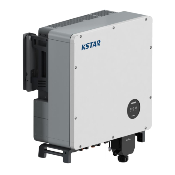
3.2 Product Appearance The appearance of the power conversion system and the introduction of external components are shown in the following figures: Figure 3-1 Front view of KAC50DP Figure 3-2 Bottom view of KAC50DP Guide for Mechanical Installation... -
Page 13: Main Power Topology
Figure 3-3 KAC50DP main circuit topology 3.4 Product Features KAC50DP power conversion system adopts advanced digital control technology to optimize control performance and improve system reliability. It is suitable for different battery charging and discharging needs and the main performance features are as follows: ... - Page 14 Ethernet 3.5.2 EMS communication scheme Figure 3-4 PC monitoring via Ethernet Through the RS485 communication line, the PCS can communicate with the EMS, and it can be monitored in real time by self-designed ESS monitoring software. RS485 Figure 3-5 EMS monitoring via RS485 3.5.3 BMS communication scheme Through the CAN communication line, the PCS can communicate with the BMS to realize data transmission.
-
Page 15: Pcs Modes And Functions
User Manual of KAC50DP Power Conversion System PCS Modes and Functions 4.1Mode Introduction 4.1.1 On-grid mode and off-grid mode Figure 4-1 System block diagram On-grid mode: connected to the public grid, following the grid voltage amplitude/phase and frequency, with island protection. -
Page 16: Pcs Functions
Charge and discharge control of energy storage battery All KAC50DP models can be charged and discharged in on-grid mode. The depth of charging and charging can be set by the user. 4.2.3 Cooling system start The cooling system will automatically start when the PCS reaches a certain power or the temperature reaches a threshold, and the speed will be adjusted steplessly. -
Page 17: Introduction To Pcs States
User Manual of KAC50DP Power Conversion System 4.3 Introduction to PCS States The PCS has 5 states in total, as shown in Table 4-1 below: Table 4-1 State and Description State Description When the DC side switch is turned on, the DC side of the... -
Page 18: 5Guide For Mechanical Installation
Safety signs “Work in progress! Do not switch on!” must be set up at all upstream switches. 5.2 Installation Process The installation process of KAC50DP power conversion system is as follows: Start Preparation before installation Mechanical installation Electrical Installation... -
Page 19: Preparation For Installation
5.3.1 Packaging inspection Check whether the equipment is damaged before installation. If any transportation damage is found, please contact the transportation company or Shenzhen Kstar New Energy Co., Ltd. and provide a photo of the damage. 5.3.2 Checking delivery list... -
Page 20: Machine Transportation
5.3.4 Requirements of installation environment Please confirm the following environment requirements before installing the power conversion system: Table 5-3 Environmental Requirements Item Requirement Temperature -20℃~50℃ <95% (no Humidity condensation) 5.4 Machine Transportation 5.4.1 Transport Instructions Transport the power conversion system with packaging as much as possible in order to keep it in a better protective state. -
Page 21: Positioning And Fixing
User Manual of KAC50DP Power Conversion System Handle with care to avoid damage to the power conversion system due to excessive collision and friction in the transportation environment. Protect against moisture and avoid rain or moisture on the PCS. 5.5 Positioning and Fixing 5.5.1 Space requirements... - Page 22 5.5.2 Model dimensions The mechanical dimensions of the KAC50DP power conversion system are shown in the figure below. Users can design and install according to this data. Figure 5-3 Dimensions of KAC50DP model 5.5.3 Hanger installation The bottom of the KAC50DP power conversion system must be reliably connected to the bottom of the foundation.
-
Page 23: Air Duct Design And Installation
5.6.1 Forced air cooling system KAC50DP power conversion system use forced air cooling for heat dissipation. 5.6.2 Ventilation environment In order to meet the ventilation requirements of the KAC50DP power conversion system, the installation environment must meet the following requirements: ... -
Page 24: 6Electrical Installation Instructions
6A, and the connecting wires on the same side should be of the same specification and type. Kstar has given the reference requirements of various interface cables. Users can refer to the design related cables according to the table below. -
Page 25: Fixing And Protection Of Connecting Cables
User Manual of KAC50DP Power Conversion System Table 6-2 Spacing between Signal Cables and Power Cables Parallel line length Min space distance ※ The data cable should be routed as close as possible to the ground or supporting wires, such as supporting beam, steel channel, metal rail, etc. - Page 26 Grounding: 6.3.2 Cable protection Cable protection includes communication cables and power cables. The protection methods are as follows: Protection of communication cables: The communication cables may be torn off or fall off from the wiring terminal easily during construction as they are thin. It is recommended to connect the power circuit first.
-
Page 27: Dc Side Wiring
A total of 3 MPPTs, the MPPT voltage access range is 350V~1000V, and the max DC current of each MPPT is 40A. The max PV input power of a single KAC50DP power conversion system is 75KW. Please refer to Section 6.5 for the location of the wiring ports. -
Page 28: Ac Side Wiring
Equipment damage and loss caused in this case are not covered by the warranty. 6.5 AC Side Wiring 6.5.1 AC connection All models of KAC50DP power conversion systems have grid connection. Only the models with bypass need to consider bypass connection. The correspondences are shown in the tables below. -
Page 29: Communication Interface
Step 3: Correctly connect the ABC (UVW) phases of the grid to the power conversion system according to Table 6-6. 6.6 Communication interface KAC50DP has two external communication interfaces, the functions are shown in the following table: Table 6-6 Parallel interface PARA connection correspondence... -
Page 30: System Grounding
Figure 6-5 Connection Diagram of COM Port 6.7 System Grounding The case of KAC50DP power conversion system needs to be reliably connected with a grounding cable. The resistance must not be higher than 4Ω, and the diameter of the grounding cable shouldn’t be less than 16mm . -
Page 31: Commissioning
Commissioning 7.1 Check before Starting Before commissioning, thoroughly check the installation of the equipment, especially whether the DC and AC terminal voltage meets the requirements of the power conversion system and whether the polarity and phase sequence are correct. Check whether all connections have met the requirements of relevant standards and whether the system is properly grounded. -
Page 32: Power On/Off Operation Process
Step 4: Check other content After completing the above-mentioned inspection, you need to carefully check the following items to ensure that they are correct. All connections are made according to the contents of Chapter 6 of this manual. The switches on AC side and DC side are disconnected, that is, in “OFF”... - Page 33 User Manual of KAC50DP Power Conversion System a quick response. Commissioning...
-
Page 34: Maintenance And Troubleshooting
If a malfunction still can’t be solved with the help of this manual, please contact Shenzhen Kstar New Energy Co., Ltd. and provide the following information so that we can provide you with better services: ... - Page 35 User Manual of KAC50DP Power Conversion System Warning If only the switch is disconnected, the cable connection terminals inside the power conversion system are still live! Before opening the machine cover and starting the formal maintenance work, not only the switch, but also the front and rear circuit breakers of the power conversion system must be disconnected.
-
Page 36: Troubleshooting
If it is necessary to replace products of other manufacturers or different models of the same manufacturer, it must be analyzed and confirmed by Kstar in advance, or else Kstar shall not be liable for any casualties or property losses that may be caused thereby. - Page 37 User Manual of KAC50DP Power Conversion System Fault type Treatment method Disconnect the DC switch and check the DC side voltage and the Low battery voltage configuration of the energy storage battery Disconnect the DC switch and check the DC side voltage and the...
- Page 38 When the DC voltage of the energy storage battery exceeds the allowable voltage DC over/under range, the power conversion system will stop working, and display the fault type voltage protection on the PC or EMS. The power conversion system can quickly detect the abnormal voltage and react. When the power conversion system detects that the grid voltage exceeds the Grid over/under allowable voltage range, it will stop working, and display the fault type on the PC...
- Page 39 User Manual of KAC50DP Power Conversion System The fan of the power conversion system has an automatic detection function. When it is detected that the fan is not running, it can quickly send fault information Fan failure protection to the DSP. The DSP will issue an instruction to stop the power conversion system, and it will send a warning signal at the same time and display the fault type on the PC or EMS.
-
Page 40: Appendix 1: Technical Parameters
Appendix 1: Technical Parameters Model KAC50DP PV input parameters Max. input voltage 1000V d.c. MPPT voltage range 350~800V d.c. Rated voltage 667V d.c. Rated power 75kW No. of MPPT Max. input current per MPPT Max. short-circuit current per MPPT Battery input parameters... - Page 41 Protection grade IP65 Overvoltage level (DC) OVC II Overvoltage level (AC) OVC III Operating temperature range -25℃~+60℃(45℃derating) Relative humidity (no condensation) 0~100% Cooling mode Intelligent air cooling Max. working altitude 3000M Display Communication interface CAN/RS485 Maintenance and Troubleshooting...
-
Page 42: Appendix 2: Quality Assurance
Appendix 2: Quality Assurance For products that fail during the warranty period, Shenzhen Kstar New Energy Co., Ltd. will repair or replace with new products free of charge. Evidence During the warranty period, the customer needs to show the invoice and date of purchasing the product. - Page 43 Shenzhen Kstar New Energy Co., Ltd. Address: Kstar Industrial Park, No. 7 Road, West District, High-tech Park, Guangming New District, Shenzhen Zip code: 518106 After-sales service hotline: 400-700-9662 URL: www.kstar.com.cn E-mail: service@kstar.com.cn ※The product size and parameters are subject to change without prior notice.
Need help?
Do you have a question about the KAC50DP and is the answer not in the manual?
Questions and answers