Table of Contents
Advertisement
Quick Links
Advertisement
Table of Contents

Related Manuals for Megatron EPA 200

Summary of Contents for Megatron EPA 200
- Page 1 EPA 200 PROCESS CONTROLDEVICE USER MANUAL KK-EPA.004Rev No:3 20.12.19...
-
Page 2: Table Of Contents
INDEX INDEX....................................2 1.TECHNICALSPECIFICATIONS............................4 2. MECHANICALDIMENSIONS ............................4 3. CONNECTIONS................................5 4. FRONTPANELIDENTIFICATIONS............................. 6 5. MENU TREE..................................7 6. SETUP....................................8 6.1Connectingthe Sensorto the Device.........................8 Press andholdto the PRG keyto switch to the programmingmenu................. 9 6.2.1.Setting the Scale Value ........................... 9 6.2.2SettingFactor Value............................9 6.2.3Setting CalibrationMethod ..........................10 6.2.4Start Calibration(START).......................... - Page 3 6.8.1.Hidethe Menu (HIDE)............................26 6.8.2.Lockthe Menu (LOCK) ............................27 6.8.3.PasswordDetermination(PASS)........................27 6.8.4.Return to Factory Settings(FTRY) ........................27 6.8.5.Restart the Device(RESET) ..........................28 7. OTHERSETTINGS................................28 7.1.DisplayMenu ................................28 7.1.1.DecimalPoint (POINT)............................28 7.1.2.TareFunction(TARE)............................29 7.1.2.1.Event ................................29 7.1.2.2.Input................................29 7.1.3.ScreenRefreshRate (REFRS) ..........................30 7.1.4.Prevention for ScreenFlicker(FILTR)......................31 7.1.4.1.AVRGE(AverageCalculation):........................31 7.1.6.B.LABL(Identifying the First Lineon the Screen)....................35 8.
-
Page 4: Technicalspecifications
1.TECHNICAL SPECIFICATIONS 50/60Hz AC/DC Supply Voltage 85-265V 50/60 Hz Power Consumption 9 VA/2,7Watt Maximum Pot: mV/V: 0-10V: Sensor Supply Voltage 0-5V: 0,5-4,5V: 4-20mA: CANopen: 100mA Max Sensor Supply Current SamplingRate 3.5kHz Input Resolution 16 bit ThermocoupleResolution 19 bit RTDResolution 15 bit Potentiometer, 0-10V, 0.5-4.5V, 0-5V, 4-20mA, 0-20mA, 3,33mV/V, 2mV/V, AnalogueInputs 2,5mV/VRatiometric, Thermocouple(K, J, N, R, S, T,E and B type), RTD... -
Page 5: Connections
3. CONNECTIONS Supply Voltage 24VAC/DCor Digital 85/265VAC Communication Relay Output 3 Analogue Outputs OUT-3 and Tare Input (optional) Thefollowing table showsthe pin Relay Output 2 numbers. OUT-2 Sensor Inputs Relay Output 1 OUT-1 Analogue Digital Conn. Outputs RS485 4-20mAOutput 0-20mAOutput RS232 Signal 0-10V Output... -
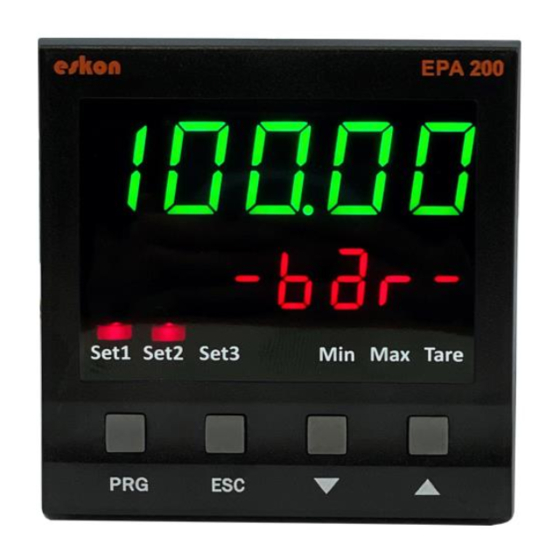
Page 6: Frontpanelidentifications
SAFETYWARNINGS Always follow the instructions andinstructions in the operating instructions before making the connections and duringuse. 2. Please checkthe power supplytype before you connect energyto your device. Duringthe operation, be sure to mount it firmly on the panel to be usedagainstfalling, sliding, shakingand shaking. -
Page 7: Menu Tree
5. MENU TREE TopMenu SubMenu O u t - 2 O u t - 3 S C A L E LABEL U N I T P O I N T T A R E P O I N T R E F R S FILTR LABEL B.LABL... -
Page 8: Setup
6. SETUP 6.1 Connectingthe Sensor to the Device Potentiometer Connection 4…20mA/0…20mAConnection *2 wire connection: Sensor supplyterminal mustbe connected to terminal 22 Sensor signalterminal mustbe connected to terminal 23 mV/Volt Connection 0…10V/0…5V/0.5-4.5V Conn. *0-5Vand0.5-4.5Vconnections are madeasabove. Thermocouple Connection RTDConnection *K, J, N, R, S, T, E andB type thermocouplescanbe connected KK-EPA.004Rev No:3 20.12.19... -
Page 9: Press Andholdto The Prg Keyto Switch To The Programmingmenu
6.2Device Calibration Press and hold to the PRG key to switch to the programmingmenu. 6.2.1. Setting the Scale Value Yourdevice is automatically calibrated to the factory settings andoperates in the 0-100range.That is, the smallest value read on the sensor is 0,and the maximumvalue is 100on the display. Youcan changethis scale on calibration menu.Use the S-LOfor the minimumvalue displayed on the screen and the S-HIoption... -
Page 10: 3Setting Calibrationmethod
6.2.3 Setting Calibration Method Yourdevice has been calibrated duringproduction. If you want, you can dothis calibration accordingto your sensor. Todo that you shouldselect the calibration method onthis menu. F C A L Factory calibration (Default) 2_Pnt. 2 pointed calibration SEGnt. Multiple (Segmented) Calibration 6.2.3.1 Factory calibration (default) -
Page 11: 4Start Calibration(Start)
6.2.4 Start Calibration (START) After selecting the number of calibration, press the button to accessthe start menu. S E G . 1 ..D O N E . S T A R T X X X Thisprocess is repeated for eachsegment. -
Page 12: 2Changingquickset Values
6.3.2 ChangingQuick Set Values Youcan quicklychangethe adjustable relay set values when the device is in operation mode. S E T - 1 Press andhold the UP button to move to the nextstep.To Press and hold When you pressand holdto the PRG key , the enter a negative (-)value, the ESC button. - Page 13 S T A N D . When the value read in the device reaches or exceedsSet-1, the relay pulls. B A N D When the value read on the device is between Set-1A and Set-1Bvalue, relay pulls. C A T C H Thevalue read on the device remains set to the value of Set-1 by increasingor decreasing the value of the relay each time it is released for the time which is entered.
-
Page 14: 2Delay
6.4.2 Delay Therelay specifies in secondshow longit will active and inactive after it is switched off. If '0' is entered as a zerovalue in the Stand function, the relay will remain drawn unlessthe relay output condition changes. delay O U T - 1 O U T When you pressand hold to the PRG key, the value... -
Page 15: Offsetvalue
6.4.4. OffsetValue If you want to add offset to the entered set value, this menu is used. All set values are, as much as ofset value isshifted forward and if it is selected negative then it is shifted backwards. ofset O U T O U T - 1 When you pressand... -
Page 16: Sensorselection (Snsor)
* Youcan also set other relay outputs in the same way. 6.5. ANALOGUEOUTPUT SETTINGS If your EPA 200,which is specially manufactured accordingto your order, has analogue output module, you can makethe necessary settings on this menu. 6.5.1. Source Type Selection for AnalogOutput (SOURC) Under the Typemenu,any of the following analogue SOURCEtypes can be selected. -
Page 17: Analogueoutputtypeselection (Type)
Source Types: Prb.tmp The sensoror thermocouple which is connected are selected as source. A m b . t m p Ambient temperature information is selected as source. Can.dt1 CANline information from the 1st data is selected as the source. Can.dt2 CANline information from the 2nddata is selected as the source. -
Page 18: Analogueoutputon/Off(Cond)
6.5.3. Analogue Output ON/OFF (COND) “ON” is usedto turn onthe analogueoutput and“OFF” is usedto turn it off. cond O U T anlog When you pressand hold to the PRG key, the value in the Press andhold the PRG button. secondline starts blinking.Enter the cond desired value using... -
Page 19: Analogueoutputscale Setting
6.5.5. AnalogueOutputScale Setting On the device with the analogueoutput feature, to set the output signal to the desired scale range, SCALE mode on this menu must be ON. Then S-LO.and S-HI.values can be entered. S - L O . S C A L E S C A L E O N / O F F When you press... -
Page 20: Digitaloutputsettings
6.6. DIGITAL OUTPUT SETTINGS WARNING: After changingthe UART or CANopensettings, you should restart the device to makethe changesto take effect. If your device hasa USB port, use MyPanelMeter, which youcan downloadfrom our website to checkyour device. Checkthe user manual of the program. 6.6.1. - Page 21 6.6.1.3. Parity Setting O U T dgtal uart Press andhold the PRG button. prITY n o n e even n o n e When you pressand holdto the PRG key the value in the second line starts blinking.Youcan select NONE, ODDor EVEN parity prITY usingthe UP and DOWN buttons.
-
Page 22: Can-Opensettings
6.6.2. CAN-OpenSettings Here you can set the baudrate, Node ID, Heartbeat, PDO etc. of your device related to CANopenprotocol. For more information on CANopen,see the EPA 200-CANopenbooklet. 6.6.2.1. Baudrate Setting O U T dgtal Press andhold the PRG button. Baud... - Page 23 6.6.2.3. Heart Beat Setting O U T dgtal Press andhold the PRG button. h . b e a t When you pressand holdto the PRG key the value in the second line starts blinking.Enter the desired Heart Beat value usingthe h .
- Page 24 6.6.2.5. Send Operation Setting O U T dgtal Press andhold the PRG button. S n d . o p . 2 5 5 2 5 5 When you pressand holdto the PRG key the value in the second line starts blinking. Enter the desired value usingthe UP and S n d .
- Page 25 6.6.2.7. RPDOSetting O U T dgtal Press andhold the PRG button. C O B I D R P D O 1 C O B I D When you pressand hold to the PRG keythe value in the secondline starts blinking.Enter the desired value usingthe UP and Thenew ID value you confirmed with the DOWN buttons.
-
Page 26: Keytone(Sound) Setting
6.7. KEY TONE(SOUND) SETTING When you pressany key on your device, you can turn the beep soundon andoff on this menu. Use ONto turn on the sound,OFF to turn it off. S O U N D When you pressand hold O U T O F F to the PRG keythe value... -
Page 27: Lockthe Menu (Lock)
6.8.4. Return to Factory Settings(FTRY) You can return the EPA 200 to its factory settings at any time. Press PRG key to come to this menu to return to the factory settings. Here you are goingto face the PASS? Youneed to enter 12345,which is the factory password,not the user passwordyou specified on the password screen. -
Page 28: Restart The Device(Reset)
PASSP S E C U R F T R Y Press andhold the PRG button. S U R E . P 1 2 3 4 5 After confirmingthe passwordwith the PRG When you pressand holdto the PRG key the button, a menu appearsaskingyou if you are value in the secondline starts blinking.Enter sure. -
Page 29: Tarefunction(Tare)
7.1.2.2. Input If your EPA 200,which is manufacturedspecifically for your order, has the Digital TareInput module, you can makesettings from the INPUT menuunder the Tare menu. TheEDGE option determinesat which edgeof the tare signalto the modulewill activate the tare function. -
Page 30: Screenrefreshrate (Refrs)
I N P U T D I S P T A R E Press andhold the PRG button. E D G E RISE O F F O F F When you pressand holdto the PRG key the value in the second line starts blinking. -
Page 31: Prevention For Screenflicker(Filtr)
7.1.4. Prevention for ScreenFlicker (FILTR) YourEPA 200device is programmedto display the signalsit receives from the sensor connected to it by its special algorithmsand to show it in the mostaccurate way. But; Youcan solve this problemwith the flickering filtering method that appears onthe screen for various reasons suchas noise in the surroundings,sensordisturbances. - Page 32 7.1.4.2. LQE (Linear QuadraticEstimation): Youcan alsoactivate this filter, also knownas the Kalmanfilter, by activating STATEON. If you decrease the COVARIANCEoption of 500,the flicker on the screen will decrease; but your device will slow downthe response to the sensor's rapid movements. L Q E D I S P FILTR...
- Page 33 H Y S . FILTR D I S P Press andhold the PRG S T A T E O F F O F F When PRG is pressedand entered, the value in the secondline starts to blinking. Youcan select ON or OFF by usingDOWN and UP buttons. S T A T E Thenew screen refresh rate you confirmed with the PRG button has beenset.
- Page 34 7.1.5. LABEL (Identifying the SecondLine on the Screen) By this menu,dependingon the type of sensor that you connected to the input of the EPA200,you can select which unit to write on the 2ndline of the display. OFFis selected as the factory default. In this case the secondrow is empty.
-
Page 35: B.labl(Identifying The First Lineon The Screen)
Youcan also select one of the fixed font options, suchas various units or label numbers. 7.1.6. B.LABL (Identifying the First Line on the Screen) By this menu, depending on the type of sensor that you connected to the input of the EPA200, you can select which unit to write on the 2ndline of the display. -
Page 36: Operationmode Functions
8. OPERATION MODE FUNCTIONS YourEPA 200processcontroller operates in two different modes. Yourdevice operates in the programmingmodewhen the settings are changedin the operation modeand the parameters are changedin the startup screen where the readingvalue is displayed onthe sensor.This section describes the functions in operation mode. 8.1. -
Page 37: Productcoding
Null -No Temperature Input S2 - RS485 communication PT1 -PT100 Boş -No External Model S3 - USB communication PT2 -PT1000 Tare EPA 200 S4 - CANopen TR1 -Thermocouple communication T -External Tare EPA200 Analog Output Signal Supply Voltage Input Signal Type... -
Page 38: Warrantycertificate
10. WARRANTY CERTIFICATE Seller Companyʼs: Name: Address: Phone: FAX: E-mail: Invoice Date and No: Delivery Date and Address: Signature, Cachet ProductBrand: ESKON Product Code: EPA-200 Serial No: Warranty Time:2Years Thisproduct is guaranteed for 2 years against manufacturingdefects. Non-warrantysituations: Mechanical damages Damages in case of transportation User errors Other casesthan these casesare under the manufacturerʼs warranty.
Need help?
Do you have a question about the EPA 200 and is the answer not in the manual?
Questions and answers