Table of Contents
Advertisement
Quick Links
Advertisement
Table of Contents

Related Manuals for Mister EV VELOCY BOX + SENSE

Summary of Contents for Mister EV VELOCY BOX + SENSE
- Page 1 VELOCY BOX + SENSE User Manual / Technical Manual...
-
Page 2: Safety Instructions
User Manual / Technical Manual v1.2 INTRODUCTION Thank you for purchasing the Velocy BOX! We hope it will give you complete satisfaction and that its advanced features will be of great use to you. This user manual will help you familarise yourself with your Velocy BOX and ensure you take full advantage of all its features. -
Page 3: Content Of The Box
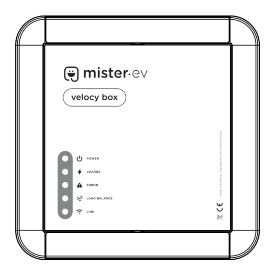
CONTENT OF THE BOX Velocy BOX Velocy SENSE (option) 1 x Velocy BOX with Type 2 or 1 cable 1 x Velocy SENSE 1 x Wall holder for Type 2 or 1 connector 1 or 3 x Measuring probe(s) 1 x Drilling template 1 x Power supply OVERVIEW 1. - Page 4 User Manual / Technical Manual v1.2 1. Power indicator: Lit when the device is switched on. 2. Error indicator: Indicates the presence of a fault (see Troubleshooting on page 11). 3. Load Balance indicator: Lit when the charging power is reduced (see Energy management on page 5).
-
Page 5: Energy Management
STARTING AND STOPPING THE CHARGING PROCESS 1. Open your vehicle's charging port (refer to your vehicle manual) 2. Remove the plug from its wall holder and connect it to your vehicle. 3. The indicator lights up after a few seconds. If it does not, refer to the Troubleshooting section on page 11. - Page 6 User Manual / Technical Manual v1.2 These instructions are intended for professionals trained and authorised to install electric vehicle charging equipment. Failure to comply with these instructions may invalidate the manufacturer's warranty. INSTALLATION - CONFIGURATION : VELOCY BOX (FRONT COVER) 1.
- Page 7 2. Wireless module (Velocy SENSE option) : This button is used to pair the Velocy BOX with the Velocy SENSE. Pairing is carried out at the factory, so this procedure is not necessary on a new device. In the event of an after-sales service requiring the replacement of one of the radio modules, it may be necessary to carry out this procedure to re-establish communication between the Velocy BOX and the Velocy SENSE.
- Page 8 User Manual / Technical Manual v1.2 INSTALLATION - MOUNTING AND WIRING: VELOCY BOX 1. Insert the power cable into the cable gland and connect it to the power terminals. In the case of a single-phase supply, only wire L1, do not bridge L1 - L2 - L3. CAUTION: leave 20cm of cable unattached to the wall so that the box can be rotated freely to gain access to the rear screws.
- Page 9 INSTALLATION - MOUNTING AND WIRING: VELOCY BOX 1. Wired load shedding terminal block : If you don't have the optional Velocy SENSE box, you can use the Velocy BOX's energy management functions with a load-shedding module of your choice fitted with an unpowered contactor.
- Page 10 User Manual / Technical Manual v1.2 INSTALLATION - MOUNTING AND WIRING : VELOCY SENSE The Velocy SENSE module must be installed close to the subscriber's main circuit breaker/meter. A domestic socket is required to connect the box's power supply unit. Depending on your configuration, clip one sensor for a single-phase installation, or 3 sensors for a three-phase installation directly onto the phase wires at the output of the customer circuit breaker.
-
Page 11: Troubleshooting
TROUBLESHOOTING Velocy BOX Indicators : O = ON * = Flashing Cause Solution Mains power temporarily insufficient. Charging restarts automatically after Charging process paused. 5 minutes. If the problem occurs too frequently, you may need to request a power increase from your energy supplier. Contact your electrician. -
Page 12: Restriction Of Liability
User Manual / Technical Manual v1.2 TROUBLESHOOTING Velocy SENSE Indicators : O = ON * = Flashing Cause Solution Configuration error. Control not The “SUPPLY GRID LIMIT" value possible. must be equal to or greater than 15A Current measurement impossible. Check the connection of the measurement probes. -
Page 13: Technical Data
● Current measurement range : 15 à 99A +/-5% MANUFACTURER The Velocy BOX and Velocy SENSE boxes are manufactured in France by ESD Electronique and distributed by : MISTER EV SAS 7, Allée Cérès 67200 STRASBOURG France Tel : +33 3 67 88 00 54 Mail : contact@mister-ev.com...
Need help?
Do you have a question about the VELOCY BOX + SENSE and is the answer not in the manual?
Questions and answers