Advertisement
- 1 Product Overview
- 2 Symbol-Explanation
- 3 Function Buttons
- 4 Advanced Functions
- 5 Operating Instructions
-
6
Measurements
- 6.1 AC/DC current measurement
- 6.2 AC inrush current measurement
- 6.3 AC/DC voltage measurement
- 6.4 Frequency or duty cycle measurements (Hz%)
- 6.5 Resistance measurement Ω
- 6.6 Continuity test
- 6.7 Diode test
- 6.8 Capacitance measurement
- 6.9 Temperature measurement
- 6.10 Non-contact AC voltage detection (NCV)
- 6.11 Live detection
- 7 Specification
- 8 Parameter List
- 9 Maintenance
- 10 Safety information
- 11 Documents / Resources
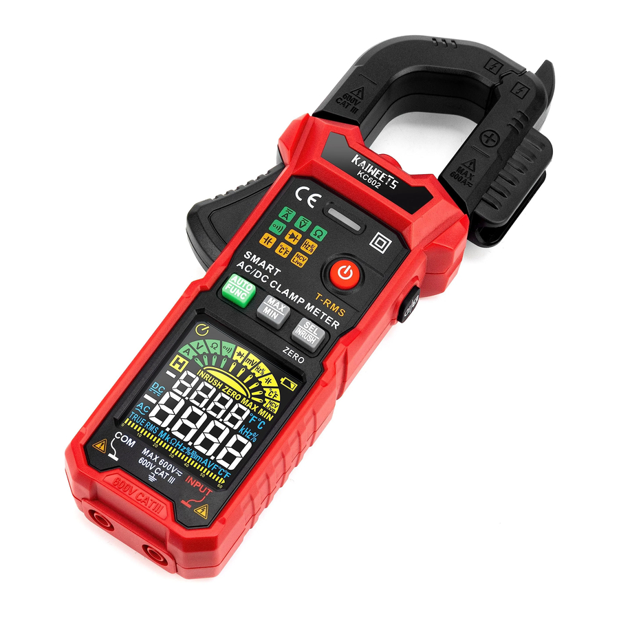
Product Overview

- NCV Probe
- Current Sensing Jaw
- TestLead Storage
- Flashlight
- Alarm Indicator LED
- Jaw Release
- Power Button
- MAX/MIN Button
- Auto Button/Function
- ZERO/SEL/Inrush Button
- LCD Display
- COM Terminal (black test lead)
- INPUT Terminal (red test lead)
- Data Hold/Flashlight Button
Symbol-Explanation

Function Buttons

Advanced Functions
AC current measurement With "Inrush" function
Inrush current is the instantaneous high input current drawn by a power supply or electrical equipment at turn-on. This arises due to the high initial currents required to charge the capacitors and inductors or transformers.

Note: The measuring time of inrush current is about 100ms.
When an electrical device powers is on, inrush current is the surge or momentary burst Of current that flows into it.
Operating Instructions
Insert and replace the batteries
Replace the batteries immediately when the symbol " " appears in the display. Disconnect the meter from power source. Remove the test leads from the measuring device, loosen the screws on the back and remove the lower half of the housing, replace the old batteries and screw the cover back on.

Turn on/off the meter
- Press and hold the
![]() key for about 2 seconds to turn on.
key for about 2 seconds to turn on. - When the measurement is finished, press and hold the
![]() key for about 2 seconds to switch off the meter.
key for about 2 seconds to switch off the meter.
 key for about 2 seconds to turn on.
Flashlight on/off
Press the  button and hold for more than 2 seconds to turn the flashlight on or off.
Data hold
Press the  button to enable or disable the data hold function.
Automatic shutdown
If there is no operation within 15 minutes after starting up. the meter will automatically shut down to save battery energy.
Cancel Auto Power off
When the meter is power off, please press and hold the  button, then turn on the instrument and then release the button. "
 " symbol will disappear and that means automatic switch-off function have canceled.
Next time you restart the machine, automatic shutdown function will be reactivated again and the display screen shows the "" symbol.
Note: After the automatic shutdown function is disabled, you need to manually power off the meter.
Calibration
- The meter automatically performs a self-test when switched on and displays "CAL" in the screen,
![]() do not press the Jaw release to open the clamp at this time.
do not press the Jaw release to open the clamp at this time. - The buzzer beeps "beep, beep, beep" indicate the completion of the self-test.
Auto-ranging
- Press the
![]() button to turn on the power supply of the meter. After the self-test is completed, the meter will display "Auto" and enter the smart measurement mode.
button to turn on the power supply of the meter. After the self-test is completed, the meter will display "Auto" and enter the smart measurement mode. - Don't need to select the measurement function, the instrument will automatically identify and measure the AC/DC voltage, AC/DC current, resistance, continuity. Current is measured by the clamp, and the other measurements will need to use the pen input.
- Read the measurement results from the display screen. The frequency is displayed when the AC signal is measured.
Note 1:
Minimum identifiable DC current 0.8A.
Minimum identifiable AC current 0.5A.
Minimum identifiable AC/DC voltage 0.8V.
Note 2: Automatic identification priority: resistance, DC voltage, AC voltage, DC current, AC current.
Connecting test leads
DO not test if leads are improperly seated.
Results could cause intermittent display readings. To ensure proper connection, firmly press leads into the input jack completely.

Measurements
AC/DC current measurement
 When making current measurements, disconnect the test leads from the Meter.
- Press the
![]() button to turn on the power supply of the meter. After the self-test is completed, the meter will display "Auto" and enter the smart measurement mode.
button to turn on the power supply of the meter. After the self-test is completed, the meter will display "Auto" and enter the smart measurement mode. - Press
![]() button, set the pointer to "A", and press the
button, set the pointer to "A", and press the ![]() button to select AC or DC current measurement function.
button to select AC or DC current measurement function. - In the DC current measurement, if the display number is not zero when the instrument is not measuring, please press and hold the
![]() button, then the meter will display "ZERO" and then you can measure.
button, then the meter will display "ZERO" and then you can measure. - Press the jaw release to open the clamp, clamp the conductor and release it until the clamp are completely closed. If the conductor is not in the center of the pliers, errors will occur.
- Read the measurement results from the display screen. The frequency is also shown on the display when measuring AC current.
 button to select AC or DC current measurement function.
 button, then the meter will display "ZERO" and then you can measure.
Note
- Use the current clamp to surround one conductor.
- If the supply and return conductors (e, g, L and N) are measured i the current Will cancel each other out and no measurement will be displayed. The cables of household appliances usually contain L and N conductors. A cable separator is required to measure with the current probe.
- If several supply conductors (e.g. L1 and L2) are measured, the currents add up.


AC inrush current measurement
- Press the
![]() button to tum on the power supply of the meter. After self-test is completed, the meter will display "Auto" and enter the smart measurement mode.
button to tum on the power supply of the meter. After self-test is completed, the meter will display "Auto" and enter the smart measurement mode. - Press
![]() button, set the pointer to "A", and press the
button, set the pointer to "A", and press the ![]() button to select inrush current measurement function and display the symbol "INRUSH".
button to select inrush current measurement function and display the symbol "INRUSH". - Then clamp the conductor to be tested, slowly release the jaw release until the clamp are completely closed, if the conductor is not in the center of the pliers, additional errors will occur.
- Turn on the tested device(such as the motor), then the instrument will measure surge current.
- Read the measurement results from the display screen.
Note: The measuring range Of inrush current is 5 ~ 600A,
AC/DC voltage measurement
 Voltage above 600 V (AC) / 600V (DC) cannot be measured! When measuring high voltage,
 ![]() pay special attention to safety to avoid electric shock or injury.
pay special attention to safety to avoid electric shock or injury.
- Press the
![]() button to tum on the power supply of the meter. After self-test is completed, the meter will display "Auto" and enter the smart measurement mode.
button to tum on the power supply of the meter. After self-test is completed, the meter will display "Auto" and enter the smart measurement mode. - Press
![]() button, set the pointer to "V", and press the
button, set the pointer to "V", and press the ![]() button to select AC or DC voltage measurement function.
button to select AC or DC voltage measurement function. - Insert the red probe in "INPUT" jack, insert the black probe in "COM" jack.
- Contact the probe to the measured circuit (connect to the measured power supply or circuit in parallel).
- Read the measurement result on the screen. When the AC voltage is measured, the frequency is displayed on the display screen.


Frequency or duty cycle measurements (Hz%)
- Press the
![]() button to turn on the power supply of the meter. After the self-test is completed, the meter will display "Auto" and enter smart measurement mode.
button to turn on the power supply of the meter. After the self-test is completed, the meter will display "Auto" and enter smart measurement mode. - Press
![]() button, set the pointer to the "Hz/%" position.
button, set the pointer to the "Hz/%" position. - Insert the red probe in "INPUT" jack, insert the black probe in "COM" jack.
- Connect the meter in parallel to the power supply or load to be tested.
- Read the measurement result on the screen.
![]()

The "mV" gear voltage measurement frequency:
- Range: 10Hz ~ 2 kHz
- Sensitivity of signal: >50mV (RMS), sine wave
The "V" gear voltage measurement frequency:
- Range: 10Hz ~ 2 kHz
- Sensitivity of signal: >0.5V(RMS), sine wave
The current measurement frequency:
- Range: 10Hz ~ 2 kHz
- Sensitivity of signal: >12A(RMS), sine wave
The "Hz/%" gear:
- Frequency range: 5Hz ~ 10MHz
- Voltage range: >2.5V RMS (The higher the frequency, the higher the voltage)
Note: Overload protection: 250V.
Resistance measurement Ω
- Press the
![]() button to turn on supply self-test is meter will display "'Auto" and enter the smart measurement mode,
button to turn on supply self-test is meter will display "'Auto" and enter the smart measurement mode, - Press
![]() button, set the pointer to the "Ω" position.
button, set the pointer to the "Ω" position. - Insert the red probe in "INPUT" jack, insert the black probe in "COM" jack.
- Contact the probe to the measured circuit or resistance.
- Read the measurement result on the screen.
![]()

Note: When measuring resistance on a circuit, the measured value might be influenced by other circuits.
Continuity test
- Press the
![]() button to turn on the power supply of the meter. After the self-test is completed, the meter will display "Auto" and enter the smart measurement mode.
button to turn on the power supply of the meter. After the self-test is completed, the meter will display "Auto" and enter the smart measurement mode. - Press
![]() button, set the pointer to the "
button, set the pointer to the "![]() " position.
" position. - Insert the red probe in "INPUT" jack, insert the black probe in "COM" jack.
- Contact the probe to the measured circuit or resistance.
- If the resistance or circuit of the measured resistance is less than 50Ω, the buzzer sounds and the alarm indicator light is on.

 " position.
Note: When measuring resistance on a circuit, the measured value might be influenced by other circuits.
Test Voltage Approx, 1V
Overload protection: 250V
Diode test
- Press the
![]() button to tum on the power supply of the meter. After self-test is completed, the meter will display "Auto" and enter smart measurement mode.
button to tum on the power supply of the meter. After self-test is completed, the meter will display "Auto" and enter smart measurement mode. - Press
![]() button, set the pointer to the "
button, set the pointer to the "![]() " position.
" position. - Insert the red probe in "INPUT" jack, insert the black probe in "COM" jack.
- Touch the diode anode with the red probe, the black probe contacts the diode cathode.
- Read the measurement result on the screen.
- If the probe polarity is opposite to the diode polarity, the meter shows "OL", which can be used to distinguish the anode and cathode.
 " position.
TO avoid electrical shock when testing diodes in a circuit, make sure the power to the circuit is turned off and all capacitors are discharged.
Overload protection: 250V
Capacitance measurement
- Press the
![]() button to tum on the power supply of the meter. After self-test is completed, the meter will display "Auto" and enter smart measurement mode.
button to tum on the power supply of the meter. After self-test is completed, the meter will display "Auto" and enter smart measurement mode. - Press
![]() button, set the pointer to the "
button, set the pointer to the "![]() " position.
" position. - Insert the red probe in "INPUT" jack, insert the black probe in "COM" jack.
- Contact the probe to the measured circuit or capacitance.
- Read the measurement results from the display screen after the display is stable.
 " position.
Note: It will take times to stable when you measure large capacitance.
Overload protection: 250V
Temperature measurement
- Press the
![]() button to tum on the power supply of the meter. After self-test is completed, the meter will display "Auto" and enter smart measurement mode.
button to tum on the power supply of the meter. After self-test is completed, the meter will display "Auto" and enter smart measurement mode. - Press
![]() button, set the pointer to the "
button, set the pointer to the "![]() " position.
" position. - Insert the K-type thermocouple into the instrument, the positive pole (red) of the thermocouple into the "INPUT" jack, and the negative pole (black) into the "COM" input.
- Contact the thermocouple probe with the measured object and read the results from the display screen.
![]()
 " position.
Note: It takes a long time for the cold end of thermocouple to be restored in the instrument to achieve thermal balance with the environment.
When measuring temperature with thermocouple, the probe of thermocouple can't touch the charged object, otherwise it may damage the instrument and may have electric shock and cause personal injury.
Non-contact AC voltage detection (NCV)
When using NCV function, remove the probe, otherwise the detection sensitivity will be affected.
- Press the
![]() button to turn on the power supply of the meter. After the self-test is completed, the meter will display "Auto" and enter the smart measurement mode.
button to turn on the power supply of the meter. After the self-test is completed, the meter will display "Auto" and enter the smart measurement mode. - Press
![]() button, set the pointer to the "NCV/Live" position.
button, set the pointer to the "NCV/Live" position. - Then NCV probe gradually approaches the detected point.
- When the weak electric field signal is induced, the "--L" symbol will be displayed, the beep will emit a slow beep sound, and the green LED indicator will light up.
- When the strong electric field signal is induced, the "--H" symbol will be displayed, the beep will emit a fast beep sound, and the red LED indicator will light up.
Note: Before using the NCV function, remove the test leads. Otherwise, the detection accuracy will be affected.
Live detection
Remove black test lead otherwise the detection sensitivity will be affected.
- Press the
![]() button to turn on the power supply of the meter. After the self-test is completed, the meter will display "Auto" and enter the smart measurement mode.
button to turn on the power supply of the meter. After the self-test is completed, the meter will display "Auto" and enter the smart measurement mode. - Press
![]() button, set the pointer to "NCV/Live" position, and press the
button, set the pointer to "NCV/Live" position, and press the ![]() button to select "Live" measurement function.
button to select "Live" measurement function. - Insert the red probe into the "INPUT" jack and remove the black probe.
- Contact the red probe with the conductor under test
- When a low voltage is detected the character "---L" is displayed, the beeper emits a slow beeping tone and the green LED lights up.
- When measure high voltage, the "--H" character is displayed, the buzzer emits a fast beeping sound, and the red LED indicator lights up. Under normal circumstances, the detected line is "LIVE" line at this time.
Specification
| Display | 6000 counters, True RMS |
| Display update frequency | approx. 3 Hz |
| Measuring impedance | 10 MQ (V range) |
| Battery | 3 x AAA (1.5V) |
| Weigh | approx. 240g |
| Dimension | 199mm x 73mm x 74mm |
| Pollution level | 2 |
| Operating temperature | 0 to +40°C |
| Operating humidity | <80% |
| Operating altitude | 0 to max. 2000 m |
| Storage temperature | -10 to +60°C |
| Air humidity in storage | <70% |
Parameter List
Reference condition: the environment temperature 18°C to 28°C, the relative humidity is no more than 80%.
accuracy: ± (% reading + word)

Maintenance
- To avoid electrical shock, disconnect test leads from the Meter before removing its back cover. Never use the Meter with the back cover removed.
- Repairs or servicing not covered in this manual should be performed only by qualified personnel.

- To avoid contamination or static damage, do not touch the circuit board without proper static protection.
- If the Meter is not used for a long time, remove the battery. Do not store the Meter in a high temperature or a high humidity environment.
Cleaning the Meter
- To avoid damaging the meter, do not use abrasives or solvents on this instrument.
- Periodically clean the Meter by wiping it with a damp cloth and mild detergent.
- Do not get water inside the case. This may lead to electrical shock or damage to the instrument.
- Wipe the contacts in the socket with a clean cotton swab soaked in alcohol.
Safety information

Read First
To avoid possible electric shock or personal injury, please obey the following instructions:
- Please read this manual carefully before using the instrument, and pay attention to safety waming information.
- Avoid using the instrument alone.
- Never measure AC current while the test leads are still insert into the input jacks.
- DO not use the meter in wet or dirty environments.
- Inspect the test leads before use. Do not use them if insulation is damaged or metal is exposed.
- Check the test leads for continuity, Replace damaged test leads before using.
- Use extreme caution when working around bare conductors or bus bars. Contact with the conductor could result in electric shock.
- Do not apply more than the rated voltage, as marked on the meter, between the terminals or between any terminal and earth ground.
- Remove test leads from the Meter before opening the Meter case.
- Never operate the Meter With the back cover removed or the case open.
- Never remove the back cover or open the case of an instrument without first removing the test leads or the jaws from a live conductor.
- Use caution when working with voltages above 30\/ ac RMS, 42V ac peak, or 60\/ dc. These voltages pose a shock hazard.
- DO not attempt to measure any voltage that might exceed the maximum range Of the Meter600V RMS.
- Do not operate the Meter around explosive gas, vapor, or dust.
- When using probes, keep fingers behind the finger guards.
- When making electrical connections, connect the common test lead before connecting the live test lead; when disconnecting, disconnect the live test lead before disconnecting the common test lead.
- Disconnect circuit power and discharge all high-voltage capacitors before testing resistance,
![]() continuity, or diodes.
continuity, or diodes. - Check the operation of the meter at a known source before and after use.
Contact us: support@Kaiweets.com

Documents / ResourcesDownload manual
Here you can download full pdf version of manual, it may contain additional safety instructions, warranty information, FCC rules, etc.
Advertisement
Need help?
Do you have a question about the KC602 and is the answer not in the manual?
Questions and answers