
Summary of Contents for Mesh S618
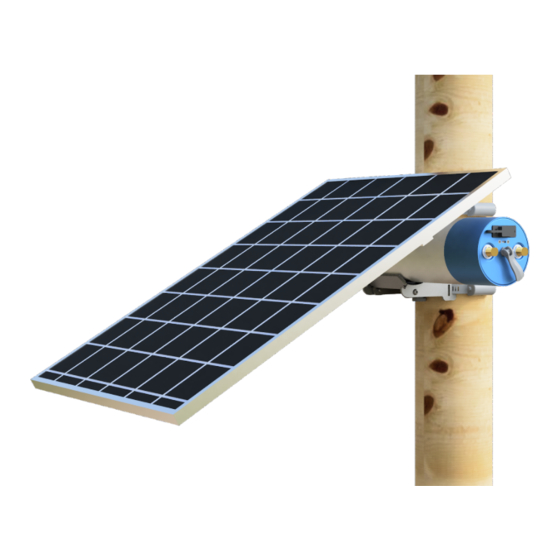
- Page 1 S618 Solar Powered Mesh Node Self-Configuring Outdoor WiFi 6 2x2 Router Operating Manual www.meshplusplus.com info@meshplusplus.com...
-
Page 2: Table Of Contents
2. Part Number Decoder 3. Node Components a. S618 node box b. Solar panel box 4. Preparation a. Unboxing the S618 node b. Unboxing the solar panel c. Overview of node ports d. Overview of USB Hub ports e. Node modes 5. - Page 3 8. Installing the Solar Panel a. Preparing to install b. Attaching onto the mount 9. Servicing the Node a. Outer case removal b. Upgrading node firmware 10. Configurations a. Cellular: SIM card installation b. Secondary panel installation c. Power over Ethernet (PoE) d.
- Page 4 Trademarks MeshPlusPlus, Mesh++, the Mesh++ logo, and S618™ are all trademarks of MeshPlusPlus, Inc. Copyrights Copyright © 2022 MeshPlusPlus, Inc. All rights reserved. No part of this publication may be reproduced or distributed in any form or by any means, or stored in a database or retrieval system, without the prior written consent of MeshPlusPlus, Inc.
-
Page 5: Warnings & Suggestions
1. Warnings & Suggestions An S618 is powered primarily via solar energy. If you would like to power it alternatively through USB-C charging, a required USB-C Power Delivery 3.0 adapter is not included. When sourcing one, please note that the adapter must be rated for at least 60W of output power (20V, 3A minimum) to properly charge the S618. -
Page 6: Electrical Safety Information
IEC 60950-1 - information technology equipment. No components failed during any safety test. b. Electrical safety information i. Installation of the S618 must comply with local and national electrical codes. ii. Compliance is required with respect to voltage, frequency, and current requirements indicated on the manufacturer’s... - Page 7 Class A Notice for FCC 1. Modifying the equipment without the authorization of Mesh++ may result in the equipment no longer complying with FCC requirements for Class A digital devices. In that event, your right to use the equipment...
-
Page 8: Part Number Decoder
2. Part Number Decoder The S618’s extended part number may be helpful to reference if its configuration needs to be verified before troubleshooting. This number can be found on a label on the outer case of the node. 1. Model Number: S618 2. - Page 9 6. Cellular Antennas: a. C2: 2 antennas installed - 2x2 EM06 4G LTE modem b. C4: 4 antennas installed - 4x4 EM160 4G LTE or 5G sub-6 GHz modems 7. Speciality Features: a. GPS (G): a module that allows the node to determine its position to an accuracy of several meters b.
-
Page 10: Node Components
3. Node Components a. S618 node box i. S618 Node Assembly 1. Node (cylinder) containing mesh radio and antennas ii. Main Mount 1. Mount that affixes the cylinder and solar panel onto a pole or wall iii. Accessory Box 1. USB Hub 2. -
Page 12: Preparation
Open the node box and the smaller accessory box inside of it, verifying that all items in the prior section were included. ii. Slide the S618 out of the box and remove the 2 cardboard endcaps on either side of the node; keep them with the box in case the node needs to be repackaged. -
Page 13: Overview Of Usb Hub Ports
(20V, 3A minimum) to function. ii. SAE ports 1. The S618 has 2 SAE ports located on each end of the device. Using the SAE to SAE cable, you may connect a solar panel to the node to power it. A single solar panel can be connected to either port, or 2 panels can be connected concurrently. -
Page 14: Node Modes
Node modes i. The S618 has a number of autoconfigured modes that determine its specific function within a mesh network. Each mode is identified by LED indicators located on the 2 LED windows on the node’s outer case. 1. LED indicators may... - Page 15 This mode can only be achieved when a node in Gateway Mode is present in the mesh and the specific node is within range of it or another node in Repeater Mode - Issue #8.
- Page 16 15% or over 90% capacity to preserve battery health - Issues #4-6. A mesh network is a self-forming WiFi network where a group of devices repeat the signal of an internet source to expand its connection. When deployed together in the same network, S618 nodes form a mesh network.
-
Page 17: Creating Your Network
5. Creating Your Network a. Setting up the mobile app i. Search for “Mesh++” on the iOS App Store or Google Play Store and install the Mesh++ mobile app. Please ensure that the app is kept up to date as we continue to add new features and enhancements. -
Page 18: Adding To Your Network
SSID for users to connect to the network. Both must be done (in any order) to create a working mesh network. ii. If your network does not already have nodes added to it, tap the Add Nodes button. - Page 19 2. Using Bluetooth: use your mobile device to scan for local nodes via Bluetooth 3. Scan QR Code: scan the QR code on a node’s serial number sticker located on its case 4. Manually: add the node’s MAC address by typing it into the app iv.
- Page 20 v. Tap Setup this Node to navigate to the node’s main options list. Here, you are able to change its name, view its MAC address , power status, add it to a network, and view the About page for additional information about the node, such as diagnostics and Bluetooth firmware - visit section...
- Page 21 WPA/WPA2 Mixed Mode. viii. Once completed, you may add other nodes to your network and create your mesh network, granted that one of the nodes has internet access. Their statuses may be viewed in the network’s page on the Dashboard tab and colors correlate to their modes.
-
Page 22: Installing The Mount
500 m (1600 ft) line-of-sight. Results may be even better depending on the antenna being utilized. ii. Line-of-sight 1. It is critical that nodes within a mesh network maintain an unobstructed line-of-sight view of each other. - Page 23 2. Ensure that all nodes in the network are completely unobstructed from each other. No tree foliage, poles, buildings, or other obstructions should come within a 6 m (20 ft) corridor between nodes for an optimal connection. iii. Height level 1.
-
Page 24: Mount Installation
3. The optimal direction for solar panel placement in the Northern Hemisphere is south-facing. The opposite is true for panel orientation in the Southern Hemisphere. 4. The optimal solar panel tilt angle can be approximated as the latitude of the location in degrees relative to ground. 5. -
Page 25: Installing The Node
7. Installing the Node a. Placing a node in its mount i. Before installing the node onto the mount, ensure that it has been successfully set up in a network and is functioning properly. If you need assistance with this, please visit section 5 - Creating Your Network. -
Page 26: Using A Node In Gateway Mode
2. The ‘Mesh++’ logos on both sides of the node are facing right-side up so that they are readable and parallel to ground level. 3. The LED windows on the node’s outer case are centered within the mount. iv. Use your fingers to begin tightening the silver clamp knob enough so that the node is held in place, but still adjustable if needed. - Page 27 source if the node is intended to be an Ethernet Gateway - an established network or router with DHCP server. iv. If you plan to charge your node via USB-C Power Delivery, the adapter must be rated for at least 60W of output power (20V, 3A minimum) in order to properly function.
- Page 28 vii. Install the USB Hub onto the mount with all its cables connected to it. 1. Make sure that the half-circle feature on the hub surrounds the silver clamp knob under the mount. The metal hub clip should have its flat side towards ground level.
-
Page 29: Installing The Solar Panel
8. Installing the Solar Panel a. Preparing to install i. Verify that your node has been clamped properly and the mount is affixed to the pole or wall securely. Unbox the solar panel, ensuring that all packaging has been removed, and locate the mounting arm. -
Page 30: Attaching Onto The Mount
b. Attaching onto the mount i. While holding the panel with one hand, use your free hand to press the closest silver gear knob until it completely touches the mount to unlock the gear and allow it to spin freely. Ensure the ribbon is being fed between the gear and turn the knob to... - Page 31 iv. Once the panel appears to be in the right position, release the aluminum gear knob or push the gear into the center (2) while jiggling the solar panel (1) to allow it to move freely. You may need to push the aluminum gear knob until the gear is shifted into the center of the mount.
-
Page 32: Servicing The Node
9. Servicing the Node a. Outer case removal The outer case may be removed to reach the node’s internal components. This is useful for adding a SIM card, storage, or servicing the node if necessary. Do not operate your node without its case installed. - Page 33 iv. Push the node’s core out of its case from the opposite side. If needed, use a non-marring tool like a mallet to tap the end without the handle before reattempting. v. As the core begins to slide out of its case, push on the heatsink to create clearance.
-
Page 34: Upgrading Node Firmware
Upgrading node firmware can only be done through the dashboard site on a computer. Please ensure to use the same Mesh++ account that is being used on your mobile app iii. The dashboard also serves as a central hub for network analysis, a node list that displays their statuses, and has the ability to reboot nodes connected to a network if needed. -
Page 35: Configurations
10. Configurations a. Cellular: SIM card installation The S618 allows you to create mesh networks by using your own cellular data plan. If you purchased a 4G LTE or 5G-LR cellular node, all you need is a nano SIM card activated with a data plan. -
Page 36: Power Over Ethernet (Poe)
i. Install the second solar panel in your desired location with a second mount. Refer to section 8 - Installing the Solar Panel It should be on the same pole as the node and the same orientation as the other panel, ensuring the panels’ shadows do not cover each other at any point throughout the day. - Page 37 PoE module separately, contact us at info@meshplusplus.com for activation. d. External antenna installation If you purchased an S618 with extended range antennas for the base model 2x2 WiFi 6 node: i. Locate the two N-type connectors on the cam handle side of the node.
- Page 38 N-type connectors and antennas. Align the first antenna on the left N-type connector. Push it onto the connector and turn the knurled section on the antenna clockwise to thread it on. The threads should be fully engaged and should turn smoothly.
-
Page 39: Troubleshooting
Debugging your node If there is an issue with installing or deploying your S618, troubleshooting may be necessary. In addition to this manual, Mesh++ offers an interactive web tool to help with the process at https://meshplusplus.com/debug . Scan the QR code to access this site →... - Page 40 3. Boot Mode: allows the user to boot the node’s system from an alternative source; SPI-NOR is standard 4. Battery Capacity: recalibrates battery level readout for more accuracy based on how many battery packs are installed into the node, or if it is powered without them 5.
- Page 41 v. Tap Diagnostic Log to enter the Diagnostic Info tab where measurements can determine certain issues a node may have, like charging or overheating. 1. NRF Time: uptime of the power management system. Under normal circumstances, this circuit will not reset. A short value is an indication that a fault occurred and power cycled the board, resetting the clock...
-
Page 42: Common Issues
negative battery current will not be able to stay online indefinitely, as the batteries will ultimately run out 9. Battery Temperature: the temperature of the battery in degrees Celsius. This value should not exceed 55°C 10. Thermistor 1 Temperature: the temperature of the PCB in degrees Celsius. - Page 43 vi. Your device must be able to communicate via Bluetooth 5 or higher for the best range. If you are using an older device with Bluetooth 4 LE (BLE), you may need to be within 30 cm (1 ft) of the node. vii.
- Page 44 vi. Unplug the battery harness from the PCB to manually power cycle it. Replug it into the PCB to reboot the node - if there is a yellow XT-90 connector on the battery harness, you may unplug and replug that instead. Issue 3: When the node is turned on, it cannot get past boot (yellow) mode.
- Page 45 disconnect and reconnect it into the node to see if the battery level changes on the mobile app. iii. If the USB Hub is being used: 1. The USB-C data transfer cable should be fully inserted into the node and the furthest USB-C port of the USB Hub. 2.
- Page 46 iii. Ensure that the SAE cable is inserted fully into both the node and solar panel arm. iv. Verify that the solar panel arm’s SAE port is soldered properly to the black junction box on the back of the panel. v.
- Page 47 2. If your connection has MAC address filtering, the node’s MAC address must be whitelisted prior. 3. If the use of a static IP is required, please contact Mesh++ info@meshplusplus.com v. Open the node’s core to verify that the internal USB-C cable is plugged into the node’s PCB.
- Page 48 Gateway Mode and is ideally less than 100 m (300 ft) line-of-sight from the node being assessed. iii. Both mesh nodes must be turned on with at least 20% battery and its LED indicators visible. Based on this issue, the LEDs should be red, indicating Recovery Mode.
- Page 49 iv. Try to connect to the same SSID using a different device. v. From the dashboard website, ensure that: 1. The SSID was successfully created and its name shows up after refreshing the network page. 2. The SSID does not have “hidden” checked, which creates a network SSID hidden from external devices such as your phone or laptop.
- Page 50 card’s notched corner must go in first and the gold pads must face down towards the batteries. 2. There are no loose antenna cables coming from the SIM card cutout on the PCB’s heatsink. 3. There are no damages to any of the cellular antennas located on the node’s inner seal plates.
-
Page 51: Warranty
12. Warranty MeshPlusPlus Inc. and MeshPlusPlus Ltd., manufacturer of this product, warrant this product to be free from defects in workmanship and materials, under normal residential use and conditions, for a period of one (1) year for the original invoice date with the exception of Lithium-ion batteries contained within device. - Page 52 www.meshplusplus.com info@meshplusplus.com...
Need help?
Do you have a question about the S618 and is the answer not in the manual?
Questions and answers