Table of Contents
Advertisement
Quick Links
Advertisement
Table of Contents

Summary of Contents for Super Hot BC-1
-
Page 2: Table Of Contents
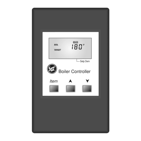
User Interface The BC-1 uses a Liquid Crystal Display (LCD) as a method of supplying information. You use the LCD in order to setup and monitor the operation of your system. The BC-1 uses three push buttons (Item, p, q) for selecting and adjusting settings. As you program your control, record your settings for future reference. -
Page 3: Description Of Display Elements
Description of Display Elements Setp Dem Symbol Description Pump °F, °C Displays when the boiler pump is in Units of measurement. operation. Stage Pointer Displays when the stage 1 and/or 2, 3, 4 Displays the operation as indicated by relay is turned on. the text. -
Page 4: Sequence Of Operation
POWERING UP THE CONTROL When the BC-1 is powered up, the control turns on all segments in the display for 2 seconds. Next, the software version is displayed for 2 seconds. Finally, the control enters into the normal operating mode. - Page 5 STAGING MODE (STGMODE) The BC-1 controls can operate up to four stages in order to supply the required target temperature. The method of staging used by the control is either P (proportional) or PID (proportional & Integral & Derivative), and is selected using the STGMODE item in the Adjust menu.
-
Page 6: Section B: Setpoint
Boiler Purge (PUMP DLY) After a demand is satisfied, the BC-1 continues to operate the boiler pump for a period of time. The length of time that the boiler pump continues to run is based on the pump DLY setting. Once the last stage of the boiler turns off, the control keeps the boiler pump running for the time selected. -
Page 7: Section C: Dedicated Dhw
CD (common demand) and the Ht D (heat demand) terminals. Once voltage is applied, the BC-1 turns on the Dem segment in the display. If the BC-1 is not in warm weather shut down (WWSD), it closes the Pmp Pmp contact, which starts the boiler pump and the control turns on the boiler pump segment in the display. -
Page 8: Section E: External Boiler
Section E: External Boiler Operation When mode 6 is selected, the BC-1 allows for an external boiler control to operate the boiler stages. In this mode, the BC-1 oper- ates the boiler pump in order to provide purging and exercising. The staging operation is provided by an external device such as an Energy Management System (EMS) or Boiler Staging control. -
Page 9: Testing
Boiler Supply / DHW Sensor Either a Boiler Supply Sensor 071 or DHW Sensor 071 may be connected to the BC-1. If a sensor is used, connect the two wires from the sensor to the Com (common sensor) and Sup/D (boiler supply/DHW sensor) terminals (4 and 6). - Page 10 Testing the Control’s Outputs The BC-1 has a built-in test routine which is used to the main control functions. The test sequence is enabled when the p button is pressed and held while in the View menu. The outputs are tested in the following sequence: Step 1: After 1 second, the pump is turned on.
-
Page 11: Control Settings
(B) DIP switch B The DIP switch B is used to select the stage mode. In 2 stage mode, the BC-1 will operate stages 1 and 2 to control the boiler temperature. In 3 stage mode, the BC-1 will operate stages 1, 2, and 3 to control the boiler temperature. For Electric Boilers, set DIP switch B to 3 stage mode. -
Page 12: Adjust Menu
Adjust Menu (1 of 2) Access Level Default Item Field Description Range Setting Sets the operating mode for the control. 1, 2, 3, 4, 5, 6 Selects the staging operation to be either automatic (automatic staging) or manual. MODE = 1, 2, 3, 4, 5 (manual staging) Minimum boiler target temperature during reset over- OFF, 70 to 210°F... - Page 13 Adjust Menu (2 of 2) Access Level Default Item Field Description Range Setting 1 (light mass) The thermal mass of the boiler used. 2 (medium mass) MODE = 1, 2, 3, 4, 5 and STGMODE = PId 3 (heavy mass) The differential that the control is to use when it is 2 to 42°F operating the boiler.
-
Page 14: Error Messages
Error Displayed Description of Error The control was unable to read a piece of information from its EEPROM. The control will stop operation until all settings in the Adjust menu have been checked by the user or installer. The control is no longer able to read the boiler outlet sensor due to a short circuit. In this case, if the boiler inlet sensor is present and operational, the control will operate using the boiler inlet sensor. -
Page 15: Typical Applications
MODE 1 MODE 4 BC-1 BC-1 Outdoor Thermostat... -
Page 16: Technical Data
Technical Data BC-1 Control Microprocessor PID control; This is not a safety (limit) control Enclosure Enclosure D, black Noryl plastic Dimensions 4-3/4” H x 2-7/8” W x 1-7/8” D (120 x 74 x 48 mm) Approvals CSA C US, meets ICES & FCC regulations for EMI/RFI.
Need help?
Do you have a question about the BC-1 and is the answer not in the manual?
Questions and answers