
Related Manuals for T.I.S. MFT-ECO

Summary of Contents for T.I.S. MFT-ECO
- Page 1 User manual © Copyright T.I.S INSTRUMENTS 2022 Release EN 1.02 - 26/07/2022...
- Page 2 © Copyright T.I.S INSTRUMENTS 2022 Release EN 1.02 - 26/07/2022...
- Page 3 © Copyright T.I.S INSTRUMENTS 2022 Release EN 1.02 - 26/07/2022...
-
Page 4: Table Of Contents
MFT-ECO TABLE OF CONTENTS 1. PRECAUTIONS AND SAFETY MEASURES ..............1.1. Preliminary instructions ......................1.2. During use ..........................1.3. After use ..........................1.4. Definition of measurement (overvoltage) category ..............2. GENERAL DESCRIPTION ....................2.1. Instrument functions ........................ 3. PREPARATION FOR USE .................... - Page 5 MFT-ECO Anomalous situations ........................6.2. DMM: Multimeter function ....................... 6.3. RPE: Continuity of protective conductors ................6.3.1. TMR mode ............................6.3.2. > φ < mode ............................. 6.3.3. Anomalous situations ........................6.4. MΩ: Measurement of insulation resistance ................6.4.1. TMR mode ............................
- Page 6 MFT-ECO 7.2. Replacement of the batteries ....................7.3. Cleaning the instrument ......................7.4. End of life ..........................8. TECHNICAL SPECIFICATIONS ..................8.1. Technical characteristics ......................8.2. Reference guidelines ....................... 8.3. General characteristics ......................8.4. Environment ..........................8.4.1. Environmental conditions for use ....................
-
Page 7: Precautions And Safety Measures
MFT-ECO 1. PRECAUTIONS AND SAFETY MEASURES The instrument has been designed in compliance with guidelines IEC/EN61557, BS7671 17th and 18th editions and IEC/EN61010, relevant to electronic measuring instruments. Before and after carrying out the measurements, carefully observe the following instructions: •... -
Page 8: During Use
MFT-ECO • We recommend following the normal safety rules devised to protect the user against dangerous currents and the instrument against incorrect use. • Only the accessories supplied with the instrument guarantee compliance with safety standards. They must be in good conditions and be replaced with identical models, when necessary. - Page 9 MFT-ECO • Measurement category I is for measurements performed on circuits not directly connected to MAINS. Examples are measurements on circuits not derived from MAINS, and specially protected (internal) MAINS-derived circuits. In the latter case, transient stresses are variable; for that reason, the standard requires that the transient withstand...
-
Page 10: General Description
MFT-ECO 2. GENERAL DESCRIPTION 2.1. INSTRUMENT FUNCTIONS The instrument can perform the following tests: • RPE Continuity test of earth, protective and equipotential conductors with test current higher than 200mA and open-circuit voltage between 4V and • MΩ Measurement of insulation resistance with continuous test voltage of 50V, 100V, 250V, 500V or 1000V DC •... -
Page 11: Preparation For Use
MFT-ECO 3. PREPARATION FOR USE 3.1. INITIAL CHECKS Before shipping, the instrument has been checked from an electric as well as mechanical point of view. All possible precautions have been taken so that the instrument is delivered undamaged. However, we recommend checking it to detect any damage possibly suffered during transport. -
Page 12: Nomenclature
MFT-ECO 4. NOMENCLATURE 4.1. INSTRUMENT DESCRIPTION CAPTION: 1. Inputs 2. LCD display 3. ,, , , SAVE/ENTER keys 4. C o m p a r t m e n t o f t h e connector for optical cable/ USB port 5. -
Page 13: Keyboard Description
MFT-ECO Fig. 3: Description of measuring leads 4.3. KEYBOARD DESCRIPTION The keyboard includes the following keys: ON/OFF key to switch on/off the instrument ESC key to exit the selected menu without confirming MENU key to back to general Menu on each moment ... -
Page 14: Initial Screen
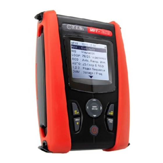
MFT-ECO 4.5. INITIAL SCREEN When switching on the instrument, the initial screen appears M F T- E C O + for a few seconds. It shows: • The instrument model T I S • The manufacturer S N : 2 2 1 0 0 1 0 0 •... -
Page 15: General Menu
MFT-ECO 5. GENERAL MENU Pressing the MENU/ESC key in any condition of the instrument allows to go back to the general menu in which internal parameters may be set, the saved measures can be displayed and the desired measuring function may be selected. -
Page 16: Country
MFT-ECO 5.1.2. Country EN - 13... -
Page 17: Electrical System
MFT-ECO 15/10 – 18:04 Move the cursor to Country by means of the arrow keys S E T (,) and confirm with ENTER. Subsequently, the displays shows the screen in order to select the reference country E u r o p e... -
Page 18: General Settings
MFT-ECO Move the cursor to Electrical system by means of the arrow 15/10 – 18:04 S E T keys (,) and confirm with ENTER. Subsequently, the display shows the screen which allows to set the followed : Vnom. 230V ... -
Page 19: Auto Start Feature
MFT-ECO Move the cursor to General settings by means of the arrow 15/10 – 18:04 S E T keys (,) and confirm with ENTER. Subsequently, the display shows the screen which allows to enable/disable the Auto Power Off : ... -
Page 20: Date And Time
MFT-ECO 5.1.6. Date and time Move the cursor to Date and time by means of the arrow 15/10 – 18:04 S E T keys (,) and confirm with ENTER. Subsequently, the display shows the screen which allows to set the system : ... -
Page 21: Operating Instructions
MFT-ECO 6. OPERATING INSTRUCTIONS 6.1. AUTO: AUTOMATIC TEST SEQUENCE (NOTRIP , RCD) This function allows to perform in automatic sequence the following measurements (only for TN systems): ➢ Overall earth resistance without causing the RCD tripping (NoTrip ) ➢ Tripping current and tripping time of General RCD type A/F (... - Page 22 MFT-ECO Fig. 5: Instrument connection in L-N-PE single phase system by means of single cables and remote switch probe Fig. 6: Instrument connection in L-L-PE split phase system through mains plug Fig. 7: Instrument connection in L-L-PE split phase system by means of single cables and remote switch probe 15/10 –...
- Page 23 MFT-ECO Use the , keys to select the parameter to be modified, and the , keys to modify the parameter value ➢ MODE 3-wire connection is the fixed mode ➢ IΔn The virtual key allows setting the nominal value of the RCD’s tripping current, which may be: 6mA, 10mA, 30mA ➢...
- Page 24 MFT-ECO appears on the display. After approx. 20s the NoTrip ends and instantaneously the values of Z L-N, L-PE, SCMin, appears on the display. If the results are correct I s c = 1 4 3 7 A Z L - N = FCMin 0 .
- Page 25 MFT-ECO 30mA MODE IΔn Type 15/10 – 18:04 In case of negative result of the NoTrip and/or A U T O >199Ω), the auto test is automatically blocked, the L-PE message “NOT OK” is shown and the screen to the side is displayed.
-
Page 26: Anomalous Situations
MFT-ECO Anomalous situations 15/10 – 18:04 If the instrument detects an L-N or L-PE voltage higher A U T O than the maximum limit (265V), it does not carry out the test and displays a screen like the one to the side. Check... -
Page 27: Dmm: Multimeter Function
MFT-ECO conductor, it does not carry out the test and displays a screen like the one to the side I s c = - - - A Z L - N = - - - Ω I f c = - - - A Z L - P E = - - - Ω... - Page 28 MFT-ECO Press the MENU key, move the cursor to DMM in the main 15/10 – 18:04 D M M menu by means of the arrow keys (,) and confirm with ENTER. Subsequently the instrument displays a screen F R E Q .
-
Page 29: Rpe: Continuity Of Protective Conductors
MFT-ECO 6.3. RPE: CONTINUITY OF PROTECTIVE CONDUCTORS This function is performed in compliance with standards IEC/EN61557-4, BS7671 17th/ 18th edition and allows measuring the resistance of protective and equipotential conductors. CAUTION • The instrument can be used for measurements on installations with... - Page 30 MFT-ECO than the set limit, the instrument emits a continuous acoustic signal. To stop the test, press the GO/STOP key or the START key on the remote lead again • >φ< Compensation of the resistance of the cables used for measurement. The instrument automatically subtracts the value of cable resistance from the measured resistance value.
- Page 31 MFT-ECO > φ< MODE Use the , keys to select the parameter to be modified, and the , keys to modify the parameter value: ➢ MODE this virtual key allows setting the test mode. The following options are available: STD, TMR ➢...
-
Page 32: Tmr Mode
MFT-ECO CAUTION If message “Measuring…” appears on the display, the instrument is performing measurement. During this whole stage, do not disconnect the test leads of the instrument from the conductor under test At the end of the measurement the instrument shows on 15/10 –... - Page 33 MFT-ECO 2.00 0.01 Ω Ω Time > φ< MODE 15/10 – 18:04 At the end of the set duration time, the instrument shows R P E on the display the maximum value between all the partial measurements performed and the message "OK" in case 0 .
-
Page 34: Φ < Mode
MFT-ECO 6.3.2. > φ < mode Fig. 12: Compensation of single cables and remote lead resistance Use the , keys to select the the virtual key > φ < Connect the alligator clips and/or test leads and/or remote prove to the conductor to be tested as in in Fig. -
Page 35: Anomalous Situations
MFT-ECO 6.3.3. Anomalous situations In case the detected value is higher than the set limit, the 15/10 – 18:04 R P E instrument gives a long acoustic signal and displays a screen similar to the one reported here to the side 4 . -
Page 36: Mω: Measurement Of Insulation Resistance
MFT-ECO If the instrument detects at its terminals a voltage higher 15/10 – 18:04 R P E than 3V it does not perform the test, it emits a prolonged acoustic signal and displays a screen like the one on the - - - Ω... - Page 37 MFT-ECO Fig. 14: Insulation between L-N-PE with single cables and remote lead (MAN and AUTO) Fig. 15: Insulation between L-N-PE by means of Mains plug (MAN and AUTO) Fig. 16: Insulation between L-PE by means of Mains plug (TMR mode)
- Page 38 MFT-ECO Fig. 17: Insulation between L-PE by means of single cables (TMR mode) Fig. 18: Insulation between L-PE by means of single cable and remote lead (TMR mode) M Ω 15/10 – 18:04 Press the MENU key, move the cursor to MΩ in the main menu by means of the arrow keys (,) and confirm with...
- Page 39 MFT-ECO We suggest setting the value of the voltage supplied while measuring and the minimum limit to consider the measure correct according to the prescriptions of the reference standard (see § 10.2) Insert the green and black connectors of the single cables into the corresponding input leads B1, B3, B4 ( MAN and AUTO modes) or B1, B3 (TMR mode) of the instrument.
-
Page 40: Tmr Mode
MFT-ECO instrument shows on the display the message "OK" in case of a positive result (value higher than the set > 9 9 9 M Ω minimum limit threshold) or "NOT OK" in case of negative result (value lower than the minimum limit 5 1 2 V threshold set). - Page 41 MFT-ECO set showing the "Measuring…" message. The Vt = T = 10 s instrument shows the message "OK" on the display in 523V case of a positive result (value higher than the set PI = - - - DAR = - - - minimum threshold) or "NOT OK"...
-
Page 42: Auto Mode
MFT-ECO 6.4.2. AUTO mode With the arrow keys (,) select the "AUTO" option in M Ω 15/10 – 18:04 the "Mode" section. The instrument displays a screen like the one shown on the side. Set the duration of the - - - MΩ Vt... -
Page 43: Anomalous Situations
MFT-ECO 6.4.3. Anomalous situations If the instrument fails to generate the nominal voltage, it M Ω 15/10 – 18:04 emits a long acoustic signal to indicate the negative result of the test and displays a screen like the one on the side 0 . - Page 44 MFT-ECO test > 524 V MΩ Not OK – Check loads AUTO 500V 1.00MΩ MODE Vtest Lim. At the end of the test, if the value of the test voltage is M Ω 15/10 – 18:04 lower than the nominal value, the instrument displays a screen like the one on the side 0 .
-
Page 45: Rcd: Test On Differential Switches
MFT-ECO 6.5. RCD: TEST ON DIFFERENTIAL SWITCHES This function is performed in compliance with standard IEC/EN61557-6, BS7671 17th edition and allows measuring the tripping time and current of molded case differential switches of type A/F ( ), AC ( ), B/B+ (... - Page 46 MFT-ECO • Some combinations of test parameters can be not available in compliance with the technical specification of the instrument and the RCD tables (see § 8.1 – the empty cells of RCD tables means not available situations) • RCD DD option is not included in AUTO sequence function The following operating modes are available: •...
- Page 47 MFT-ECO Fig. 19: Connection for single-phase L-N-PE system by means of mains plug EN - 44...
- Page 48 MFT-ECO Fig. 20: Connection for single-phase L-N-PE system with single cables and remote switch probe Fig. 21: Connection for three-phase L1-L2-L3-N system by means of single cables and remote switch probe Fig. 22: Connection for L1-L2-PE split-phase system by means of single cables and remote switch probe Fig.
- Page 49 MFT-ECO Press the MENU key, move the cursor to RCD in the main menu by means of the arrow keys (,) and confirm with ENTER. Subsequently the instrument displays a screen similar to the one reported here to the side in case of single-phase L-N-PE electrical system selected (see §...
- Page 50 MFT-ECO EN - 47...
-
Page 51: Auto Mode
MFT-ECO 6.5.1. AUTO mode EN - 48... - Page 52 MFT-ECO 15/10 – 18:04 Press the GO/STOP key on the instrument, the START A U T O key on remote lead or the AutoStart feature (see § 5.1.5). The instrument will start the measurement 0 ° 1 8 0 °...
-
Page 53: Auto Mode
MFT-ECO AUTO 30mA MODE IΔn Type 6.5.2. AUTO mode 15/10 – 18:04 Press the GO/STOP key on the instrument, the START A U T O key on remote lead or the AutoStart feature (see § 5.1.5). The instrument will start the measurement 0 °... -
Page 54: X1, X5 Modes
MFT-ECO 15/10 – 18:04 In case of positive result (all tripping times comply with A U T O what indicated in 10.4) of the all test sequentially performed the “OK” message is shown and the screen to 0 ° 1 8 0 °... -
Page 55: Mode
MFT-ECO 6.5.4. mode The standard defines the tripping times for RCDs at nominal current. The mode is used to detect the tripping time at tripping current (which could also be lower than the nominal voltage. Press the GO/STOP key on the instrument, the START key on remote lead or the AutoStart feature (see §... -
Page 56: Dd Mode
MFT-ECO 6.5.5. DD mode The standard IEC62955 defines the tripping times and current for RCD-DD (Detecting Devices) types at nominal current of 6mA only. The x1 and options are only available in this mode. Press the GO/STOP key on the instrument, the START key on remote lead or the AutoStart feature (see §... -
Page 57: Ccid Mode (Tn Systems - Usa Country)
MFT-ECO When the RCD trips and separates the circuit, if the tripping current and tripping time are NOT within the limits reported in § 8.1, the instrument gives a double acoustic signal which signals the “NOT OK” message is shown and the screen to the side is... - Page 58 MFT-ECO CAUTION If message “Measuring…” appears on the display, the instrument is performing measurement. During this whole stage, do not disconnect the test leads of the instrument from the mains. When the RCD trips and breaks the circuit, if the tripping current and tripping time are within the limits reported in §...
-
Page 59: Anomalous Situations
MFT-ECO 6.5.7. Anomalous situations If the instrument detects a frequescy higher than the maximum limit (63Hz), it does not carry out the test and displays a screen like the one to the side R C D 15/10 – 18:04 - - - - - - FREQ. - Page 60 MFT-ECO If the instrument detects a dangerious voltage on PE conductor it provides the warning screen shown to the side and blocks the execution of the tests. Check the PE conductor and earth plant efficiency R C D 15/10 – 18:04...
- Page 61 MFT-ECO If the instrument detects the absence of the signal to terminal B3 (PE conductor), it provides the warning screen shown to the side and blocks the execution of the tests R C D 15/10 – 18:04 - - - - - - FREQ.
- Page 62 MFT-ECO If the instrument detects a dangerious contact voltage Ut (over the set limit 25V or 50V) in the starting pre-test, it provides the warning screen shown to the side and blocks the execution of the tests. Check the PE conductor and earth plant efficiency R C D 15/10 –...
-
Page 63: Loop: Line Impedance/Loop And Overall Earth Resistance
MFT-ECO 6.6. LOOP: LINE IMPEDANCE/LOOP AND OVERALL EARTH RESISTANCE This function is performed in compliance with standard IEC/EN61557-3, BS7671 17th/18th edition and allows measuring the line impedance, the fault loop impedance and the prospective short-circuit current. CAUTION Depending on the selected electrical system (TT, TN or IT) some kind of... - Page 64 MFT-ECO The measurement of line impedance or fault loop impedance involves the circulation of a maximum current according to the technical specifications of the instrument (see § 8.1). This could cause the tripping of possible magnetothermal or differential protections at lower tripping...
- Page 65 MFT-ECO Fig. 25: L-N/L1-PE test for single-phase/split-phase systems with mains plug Fig. 26: L-N/L1-PE test for single-phase/split-phase systems with cables and remote probe Fig. 27: L-N/L1-PE test for three-phase with single cables and remote probe Fig. 28: L1-L2 measurement for three-phase systems...
- Page 66 MFT-ECO Use the , keys to select the parameter to be modified, and the , keys to modify the parameter value ➢ FUNC the virtual key allows setting the measuring mode of the instrument, which may be: L-N, L-L or L-PE (single-phase/three-phase systems) or L1-PE, L1-L2 (split-phase systems) ➢...
- Page 67 MFT-ECO VL-PE=231V VL-N=232V Measuring… L-PE MODE During this whole stage, do not disconnect the R C D 15/10 – 18:04 measuring leads of the instrument from the system under test. The following screen appears on the Ipfc instrument's display. Ω...
-
Page 68: Br.cap Mode - Verify Of Breaking Capacity Of Protection Device
MFT-ECO 6.6.4. Br.Cap mode – Verify of breaking capacity of protection device Press the MENU key, move the cursor to LOOP in the L O O P 15/10 – 18:04 main menu by means of the arrow keys (,) and confirm with ENTER. - Page 69 MFT-ECO Br.Cap 15kA MODE Press the GO/STOP key on the instrument, the START L O O P 15/10 – 18:04 key on remote lead or the AutoStart feature (see § 5.1.5). The instrument will start the measurement amd the - - - “Measuring…”...
-
Page 70: Tript - Verify Of Protection Coordination
MFT-ECO Br.Cap 6.0kA MODE 6.6.5. TripT - Verify of protection coordination Press the MENU key, move the cursor to LOOP in the L O O P 15/10 – 18:04 main menu by means of the arrow keys (,) and confirm with ENTER. Subsequently the instrument... - Page 71 MFT-ECO If possible, disconnect all loads connected downstream of the measured point, as the impedance of these users could distort the test results. Perform the preliminary calibration of the test leads as described in § 6.6.2 Insert the green, blue and black connectors of the three-pin shuko cable into the corresponding input leads B3, B4 and B1 of the instrument.
- Page 72 MFT-ECO interrupted by the protection device within the time indicated by the performed selections), the “OK” message and the screen to the side is displayed by the Ω 1.03 instrument ZL-L FREQ. = 50.00Hz VL-PE=223V VL-L=387V TripT 0.2s MODE MCB-C...
- Page 73 MFT-ECO If possible, disconnect all loads connected downstream of the measured point, as the impedance of these users could distort the test results. Perform the preliminary calibration of the test leads as described in § 6.6.2 Insert the green and black connectors of the three-pin shuko cable into the corresponding input leads B3 and B1 of the instrument.
- Page 74 MFT-ECO MODE MCB-C Time In case of positive result (Z ≤ to limit impedance L O O P 15/10 – 18:04 L-PE relative to protection device within the specified time – see § 10.10), the “OK” message and the screen to the...
-
Page 75: Notrip 3-Wire Test - Verify Of Protection Against Indirect Contacts
MFT-ECO 6.6.7. NoTrip 3-wire test - Verify of protection against indirect contacts 15/10 – 18:04 Press the MENU key, move the cursor to AUTO in the L O O P main menu by means of the arrow keys (,) and confirm with ENTER. - Page 76 MFT-ECO 15/10 – 18:04 Note the correct voltage values between L-N and L-PE as A U T O shown in the screen to the side I s c = - - - A Z L - N = - - - Ω...
-
Page 77: Verify Of Protection Against Indirect Contacts (It Systems)
MFT-ECO 15/10 – 18:04 In case of negative result (Z A U T O > to limit impedance L-PE relative to protection device within the specified time – see § 10.10), the “NOT OK” message and the screen to the side is displayed by the instrument I s c = 8 9 A Z L - N = 2 . - Page 78 MFT-ECO Insert the green, blue and black connectors of the three-pin shuko cable into the corresponding input leads B3, B4 and B1 of the instrument. As an alternative, use the single cables and apply the relevant alligator clips to the free ends of the cables.
- Page 79 MFT-ECO MODE In case of negative result (contact voltage at the point L O O P 15/10 – 18:04 >50V or >25V) the “NOT OK” message and the screen to the side is displayed by the instrument the screen to the Ipfc >999...
-
Page 80: Verify Of Protection Against Indirect Contacts (Tt Systems)
MFT-ECO 6.6.9. Verify of protection against indirect contacts (TT systems) Press the MENU key, move the cursor to LOOP in the L O O P 15/10 – 18:04 main menu by means of the arrow keys (,) and confirm with ENTER. Subsequently the instrument - - - Ω... - Page 81 MFT-ECO NoTrip 2Wire 30mA MODE IΔn Press the GO/STOP key on the instrument, the START L O O P 15/10 – 18:04 key on remote lead or the AutoStart feature (see § 5.1.5). The instrument will start the measurement amd the - - - Ω...
-
Page 82: Verify Of Protection Against Indirect Contacts (Tn Systems)
MFT-ECO VL-PE=232V NOT OK NoTrip 2Wire 30mA MODE IΔn 6.6.10. Verify of protection against indirect contacts (TN systems) Press the MENU key, move the cursor to LOOP in the L O O P 15/10 – 18:04 main menu by means of the arrow keys (,) and confirm with ENTER. - Page 83 MFT-ECO If possible, disconnect all loads connected downstream of the measured point, as the impedance of these users could distort the test results. Perform the preliminary calibration of the test leads as described in § 6.6.2 Insert the green, blue and black connectors of the three-pin shuko cable into the corresponding input leads B3, B4 and B1 of the instrument.
- Page 84 MFT-ECO MODE MCB-C Time In case of positive result (calculated minimum short- L O O P 15/10 – 18:04 circuit current HIGHER than tripping current of the protection device within the specified time – see § 10.6), the “OK” message and the screen to the side is Ω...
-
Page 85: Anomalous Situations
MFT-ECO 6.6.11. Anomalous situations If the instrument detects a frequescy higher than the L O O P 15/10 – 18:04 maximum limit (63Hz), it does not carry out the test and displays a screen like the one to the side... - Page 86 MFT-ECO maximum limit (460V), it does not carry out the test and displays a screen like the one to the side. Check the Ipfc - - - connection of measuring cables ZL-L - - - Ω FREQ. = 50.00Hz VL-PE=>265V VL-L=>460V...
- Page 87 MFT-ECO If the instrument detects the absence of the signal to L O O P 15/10 – 18:04 terminal B3 (PE conductor), it provides the warning screen shown to the side and blocks the execution of the Ipfc - - -...
- Page 88 MFT-ECO MODE If the instrument detects that the phase and PE leads are L O O P 15/10 – 18:04 inverted, it does not carry out the test and a screen similar to the one reported to the side is displayed. Check...
-
Page 89: 1,2,3: Phase Sequence And Phase Concordance Test
MFT-ECO 6.7. 1,2,3: PHASE SEQUENCE AND PHASE CONCORDANCE TEST This function is performed in compliance with standards IEC/EN61557-7 and allows testing the phase sequence and concordance with 1-wire method by direct contact with live parts (not on cables with insulating sheath). - Page 90 MFT-ECO Press the GO/STOP key on the instrument or the START 1 2 3 15/10 – 18:04 key on the remote lead. The instrument will start the test. The "Touch L1" message is shown on the display to indicate the waiting for the instrument to be connected to...
- Page 91 MFT-ECO The instrument gives out a long sound until input voltage 1 2 3 15/10 – 18:04 is present. At the end of the test, if the detected phase sequence is correct, the instrument displays a screen like the one shown to the side (result "123") and the “OK”...
- Page 92 MFT-ECO EN - 89...
-
Page 93: Anomalous Situations
MFT-ECO 6.7.1. Anomalous situations EN - 90... - Page 94 MFT-ECO If the instrument detects an input voltage frequency 1 2 3 15/10 – 18:04 exceeding the allowed full scale, it will display a screen like the one to the side - - - Freq. out of range If the instrument detects an input L-PE voltage 1 2 3 15/10 –...
- Page 95 MFT-ECO EN - 92...
-
Page 96: Maintenance
MFT-ECO 7. MAINTENANCE 7.1. GENERAL INFORMATION ➢ While using and storing the instrument, carefully observe the recommendations listed in this manual in order to prevent possible damage or danger during use. ➢ Do not use the instrument in environments with high humidity levels or high temperatures. -
Page 97: Technical Specifications
MFT-ECO 8. TECHNICAL SPECIFICATIONS Accuracy is calculated as: ±[%reading + (no. of digits) * resolution] at 23°C, <80%RH 8.1. TECHNICAL CHARACTERISTICS AC TRMS voltage Range [V] Resolution [V] Accuracy 15 ÷ 460 ±(3%rdg + 2dgt) Frequency Range [Hz] Resolution [Hz] Accuracy 47.50 ÷... - Page 98 MFT-ECO Open-circuit voltage rated test voltage -0% +10% Rated measuring current: >1mA with 1kΩ x Vnom (50V, 100V, 250V, 1000V), >2.2mA with 230kΩ @ 500V Short-circuit current <6.0mA for each test voltage Safety protection: error message for input voltage >30V Line/Loop impedance (Phase-Phase, Phase-Neutral, Phase-Earth) Range [Ω]...
- Page 99 MFT-ECO ✓ ✓ ✓ ✓ ✓ ✓ 10mA B/B+ CCID 20mA B/B+ CCID ✓ ✓ ✓ ✓ ✓ ✓ 30mA B/B+ CCID ✓ ✓ ✓ ✓ 100mA B/B+ CCID ✓ ✓ ✓ ✓ 300mA B/B+ CCID ✓ ✓ 500mA 650mA...
- Page 100 MFT-ECO 999 999 ✓ ✓ 100mA 999 999 ✓ ✓ 300mA 999 999 ✓ ✓ 500mA 999 999 650mA 999 999 1000m 999 999 Table with duration of tripping time measurement [ms] - Resolution: 1ms, Accuracy:±(2.0%reading + 2digits) Test on RCD protection (DD type)
- Page 101 MFT-ECO ±(5%rdg +30dgt) 10.0 ÷ 199.9 Overall earth resistance in systems withot Neutral (2-wire) – (30mA or higher RCD) Range [Ω] Resolution [Ω] Accuracy 0.05 ÷ 9.99 0.01 ±(5%rdg +8dgt) 10.0 ÷ 99.9 100 ÷ 1999 Overall earth resistance in systems withou Neutral (2-wire) – (6mA and 10mA RCD) Range [Ω]...
-
Page 102: Reference Guidelines
MFT-ECO 8.2. REFERENCE GUIDELINES Safety: IEC/EN61010-1, IEC/EN61557-1, -2, -3, -4, -6, -10 EMC : IEC/EN61326-1 Technical documentation: IEC/EN61187 Safety of accessories: I E C / E N 6 1 0 1 0 - 0 3 1 , I E C / E N 6 1 0 1 0 - 2 - 0 3 2 , I E C /... -
Page 103: Environment
MFT-ECO 8.4. ENVIRONMENT 8.4.1. Environmental conditions for use Reference temperature: 23°C ± 5°C ; (73°F ± 41°F) Operating temperature: 0°C ÷ 40°C ; (32°F ÷ 104°F) Allowable relative humidity: <80%RH Storage temperature: -10°C ÷ 60°C ; (14°F ÷ 140°F) Storage humidity: <80%RH... -
Page 104: Service
MFT-ECO 9. SERVICE 9.1. WARRANTY CONDITIONS This instrument is warranted against any material or manufacturing defect, in compliance with the general sales conditions. During the warranty period, defective parts may be replaced. However, the manufacturer reserves the right to repair or replace the product. -
Page 105: Theoretical
MFT-ECO 10. THEORETICAL APPENDIXES 10.1. CONTINUITY OF PROTECTIVE CONDUCTORS Check the continuity of: • Protective conductors (PE), main equalizing potential conductors (EQP), secondary equalizing potential conductors (EQS) in TT and TN-S systems • Neutral conductors having functions of protective conductors (PEN) in TN-C system. -
Page 106: Insulation Resistance
MFT-ECO general, if the instrument detects values of some ohms, the test may be considered as successful. 10.2. INSULATION RESISTANCE Purpose of the test Check that the insulation resistance of the installation complies with the requirements of the applicable guidelines. This test has to be performed with the circuit being tested not powered and with the possible loads it supplies disconnected. -
Page 107: Checking Circuit Separation
MFT-ECO 10.3. CHECKING CIRCUIT SEPARATION A SELV system is a zero-category system or safety extra low voltage system characterized by power supply from an independent (e.g. batteries, small generator set) or safety source (e.g. safety transformer), protective separation from other electrical systems (double or reinforced insulation or earthed metal screen) and absence of earthed points (insulated from the earth). - Page 108 MFT-ECO EN - 105...
- Page 109 MFT-ECO EXAMPLE OF SEPARATION TEST BETWEEN ELECTRICAL CIRCUITS Insulation or safety transformer separating the circuits TEST BETWEEN ACTIVE PARTS Connect an instrument probe to one of the two conductors of the separated circuit and the other to one of the conductors of a non- separated circuit.
-
Page 110: Test On Differential Switches (Rcd)
MFT-ECO 10.4. TEST ON DIFFERENTIAL SWITCHES (RCD) Purpose of the test Checking that the General (G) and Selective (S) differential protection devices have been correctly installed and adjusted and that they maintain their characteristics over time. The check must make sure that the differential switch trips at a current not higher than its... -
Page 111: Verify Of The Breaking Capacity Of Protection Devices
MFT-ECO IV [S] > 30 Minimum non-actuating time Table 5: Tripping times for general and selective differential switches in AUS/NZ country (*) Minimum test period for current of ½ IΔn, RCD shall no trip-out (**) Test current and measurement accuracy correspond to AS/NZS 3017 requirements Measurement of tripping current for protection differential switches ➢... -
Page 112: Verify Of Protection Against Indirect Contacts In Tn Systems
MFT-ECO 230V+10% < Vmeasured < 400V- 10% Vmeasured 1.10 400V-10% < Vmeasured < 400V+ 10% 400V 1.05 10.6. VERIFY OF PROTECTION AGAINST INDIRECT CONTACTS IN TN SYSTEMS Purpose of the test The protection against indirect contacts in the TN systems must be guarantee by means a... - Page 113 MFT-ECO Parts of the system to be checked The test must necessarily be performed on TN and IT systems not protected by differential devices. Allowable values The measurement is aimed at ensuring that in every point of the system the followed relationships are satisfied: −...
-
Page 114: No Trip Test In Tn Systems
MFT-ECO Fig. 39: Example of curves relative to magnetothermal (MCB) protection The instrument allows the selection (*) of the following parameters: ➢ MCB current (B, C, K, D curves) selectable among values: 3,6,10,16,20,25,32,40,50,63,80,100,125 ➢ Nominal current Fuse BS88-2 selectable among values: 2, 4, 6, 10, 16, 20, 25, 32, 40, 50, 63, 80, 100, 125, 160, 200A ➢... -
Page 115: Verify Of Protection Against Indirect Contacts In Tt Systems
MFT-ECO The measurement is aimed at ensuring that in every point of the system the followed relationships are satisfied: ≤ Z L-PE ≤ Z where: = Impedance measured between phase and PE L-PE = Impedance measured between phase and neutral... -
Page 116: Verify Of Protection Against Indirect Contacts In It Systems
MFT-ECO Allowable values The value of earth resistance, however measured, must satisfy the following relation: < 50 / I where: = resistance measured of earth installation whose value can be determined with the following measurements: • Impedance of the fault ring (*) •... -
Page 117: Verify Of Protection Coordination L-L, L-N And L-Pe
MFT-ECO Verify that the impedance of the ground probe in which the mass are connected satisfyteh following relationship: ≤ where: L-PE impedance of the ground probe in which the mass are connected L-PE current of first fault (typically expressed in mA) - Page 118 MFT-ECO The test must be performed at the point in which the minimum short-circuit current is possible, normally at the end of the line controlled by the protection device in the normal condition of the line. The test must performed between Phase-Phase in the Three-phase...
- Page 119 MFT-ECO Z L-N = Impedance Phase-Neutral measured Z L-PE = Impedance Phase-PE measured CAUTION The instrument must be used to measure fault loop impedance values at least 10 times higher than the resolution value of the instrument in order to minimize errors.
- Page 120 MFT-ECO MEMO _______________________________________________________________________ _______________________________________________________________________ _______________________________________________________________________ _______________________________________________________________________ _______________________________________________________________________ _______________________________________________________________________ _______________________________________________________________________ _______________________________________________________________________ _______________________________________________________________________ _______________________________________________________________________ _______________________________________________________________________ _______________________________________________________________________ _______________________________________________________________________ _______________________________________________________________________ _______________________________________________________________________ _______________________________________________________________________ _______________________________________________________________________ _______________________________________________________________________ _______________________________________________________________________ _______________________________________________________________________ _______________________________________________________________________ _______________________________________________________________________ _______________________________________________________________________ _______________________________________________________________________ EN - 1...
- Page 121 MFT-ECO _______________________________________________________________________ _______________________________________________________________________ _______________________________________________________________________ _______________________________________________________________________ _______________________________________________________________________ _______________________________________________________________________ _______________________________________________________________________ _______________________________________________________________________ _______________________________________________________________________ _______________________________________________________________________ _______________________________________________________________________ _______________________________________________________________________ _______________________________________________________________________ _______________________________________________________________________ _______________________________________________________________________ _______________________________________________________________________ _______________________________________________________________________ _______________________________________________________________________ _______________________________________________________________________ _______________________________________________________________________ _______________________________________________________________________ _______________________________________________________________________ _______________________________________________________________________ _______________________________________________________________________ EN - 2...
- Page 122 MFT-ECO EN - 1...
- Page 123 TEST INSTRUMENT SOLUTIONS LTD 28 BROW WOOD ROAD, BIRSTALL – WEST YORKSHIRE - UK (T): 01924 471600 (F): 01924 471900 Email: testinstruments@btinternet.com Web: www.testinstrumentsolution.co.uk...
Need help?
Do you have a question about the MFT-ECO and is the answer not in the manual?
Questions and answers