Advertisement
Quick Links
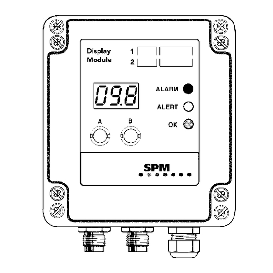
Installation of Bearing Display Modules BDM
Jumper for measuring range setting
Value display
Control buttons
Relay 1
Relay 2
Description
Bearing Display Modules measures the shock pulse values of rolling bearings in dBsv on two channels
and converts the result to analog signals, 4-20 mA. The measuring range can be jumper set on the lower
circuit board to either 0 – 80 dBsv or to 20 – 100 dBsv. Via coaxial cables with TNC connectors, the BDM
modules are connected to shock pulse transducers of type SPM 40000 (BDM-40) or of type SPM 42000
(BDM-42). The modules are supplied with 12 to 24 V DC ± 10%, source referred to earth.
The Bearing Display Modules have two relay outputs, 24 V/100 mA. The relays can be controlled by
either input channel. When using one input channel ('r 1' mode), both relays are slaved to that channel
and provide relay switching at two levels (ALERT and ALARM). When using two input channels ('r 2'
mode), each channel uses one relay which switches at the ALARM level.
Measured quantities and ranges are selected from a list of 13 programs. The user can add 7 own
programs. Programmable parameters for each input channel are the measuring range, the two alarm
levels ALERT and ALARM, and the time delay for each. The user also selects the relay mode and either
manual or automatic reset of ALARM. These parameters are input with two push-buttons.
Status display is provided by three coloured LEDs. The green LED is on while measured values are below
the ALERT level. Measured values between ALERT and ALARM on either channel trigger a yellow LED,
and a red LED lights up when a measured value exceeds one of the ALARM levels. A blinking yellow LED
indicates a system fault (incoming signal below 4 mA).
The measured value is displayed with two digits. In 'two channel mode', the status LEDs and the display
alternate between the two channels. The display shows the channel number followed by the measured
value on this channel.
The display modules can be connected to the analog input (4-20 mA analog signals) and the digital input
(relays) of a PLC.
SPM Instrument AB • Box 504 • SE-645 25 Strängnäs • Sweden
Tel +46 152 22500 • Fax +46 152 15075 • info@spminstrument.se • www.spminstrument.com
Jumper for TLT OFF
Channel 1
Channel 2
Measurement unit
stickers
Red on = ALARM
Red blinking = ALARM and
system fault
Yellow on = ALERT
Yellow blinking = system fault
Green on = power on,
no alarm
DC supply 12 to 24 V,
source referred to earth
Technical data are subject to change without notice.
ISO 9001 certified. © SPM 2004-04. 71748.B
Advertisement

Subscribe to Our Youtube Channel
Summary of Contents for SPM BDM-40
- Page 1 0 – 80 dBsv or to 20 – 100 dBsv. Via coaxial cables with TNC connectors, the BDM modules are connected to shock pulse transducers of type SPM 40000 (BDM-40) or of type SPM 42000 (BDM-42). The modules are supplied with 12 to 24 V DC ± 10%, source referred to earth.
- Page 2 1 second per channel Transducer type: SPM 40000 (BDM-40), SPM 42000 (BDM-42) Transducer cable: coaxial cable, SPM 90005-L, or 90267-L (L = length in m) Analog output: 4 to 20 mA, no galvanic separation Fault indication: ≤1 mA out = interrupted or faulty transducer line Loop resistance: max.
-
Page 3: Mechanical Installation
Analog The analog signals 4 - 20 mA can also be used in signal the AMS unit for on-line condition monitoring in – + connection with the SPM Condmaster ® Pro soft- 47 Ω 47 Ω 75 Ω –... - Page 4 Installation of Bearing Display Module BDM Jumper for setting of measuring range 0 – 80 dBsv 20 – 100 dBsv Measuring circuit board A jumper can be set at TLT OFF for test (min. 4 mA in case of TLT fault) TLT OFF (test) TLT (normal) BDM modules contain two circuit boards, the bearing measuring circuit board (lower) and the display...
- Page 5 Whenever possible, the bearing should be measured with a SPM Tester before setting alarm levels. This instrument will also show the exact initial value dBi of a bearing when shaft diameter and rpm are input.
-
Page 6: Display During Operation
Installation of Bearing Display Module BDM No. Quantity Unit 20mA No. Quantity Unit 20mA Test 0-20 mA 20.0 Vibration inch/s 1.57 Vibration mm/s Temperature °F Vibration mm/s 10.0 Percentage Vibration mm/s 20.0 Vibration mm/s 40.0 Shock pulse dBsv Shock pulse dBsv Temperature °C... -
Page 7: Alarm Reset
Installation of Bearing Display Module BDM One channel mode, programming When programming in 'one channel mode', the button A is used to go to the next step while the button B is used to make changes. You can step through the whole program and check all setting by simply pressing A. - Page 8 Installation of Bearing Display Module BDM Two channel mode, programming When programming, the point [ B ] is where you set 'two channel mode'. After that, the button A is used to go to the next step while the button B is used to make changes. You can step through the rest of program and check all setting by simply pressing A.
- Page 9 Installation of Bearing Display Module BDM Relay action in two channel mode The relays are specified 24 V/100 mA. In 'two channel mode', the user can select one of three alternative relay modes. Relay mode 'r 1' In two channel mode, the module receives analog signals on both channel 1 and channel 2. Two alarm levels can be programmed for each channel (see page 8).
- Page 10 Installation of Bearing Display Module BDM Setting alarm levels and delay 2 channel 1 channel 1. For channel 1, hold down button A until (3 s) (3 s) (3 s) either ”AL1” or ”Ch1” is displayed. For channel 2, hold down button B until ”Ch2”...
- Page 11 Installation of Bearing Display Module BDM Own programs Own program (14-20) You can make programs for any type of meas- ured quantity with a measuring range of –99 to 999 and represented by the incoming analog signal. You set 3 seconds •...
- Page 12 ........................................Measuring point, channel 2: ....................................................................Machine data: ..................................Comments: ..........................................................................................................................................................SPM Instrument AB • Box 504 • SE-645 25 Strängnäs • Sweden. Tel +46 152 22500 • Fax +46 152 15075 • info@spminstrument.se • www.spminstrument.com...
Need help?
Do you have a question about the BDM-40 and is the answer not in the manual?
Questions and answers