Table of Contents
Advertisement
Quick Links
INSTALLATION AND OPERATION MANUAL
FOR THE BASIC CONTROL PANEL (CCB2.0) FOR
FISAIR EVAPORATIVE HUMIDIFIERS
Software version 2.1 | MCCB2.0-EN-21-3
In compliance with the Rules and Standards of the European Union on Machine Safety, it is essential to read this protocol
carefully before installing any equipment.
FISAIR, S.L.U. C/Uranio, 20; PoI. Ind. Aimayr, 28330 San Martín de la Vega (Madrid) Spain.
Tel: (+34) 91 692 15 14 Fax: (+34) 91 691 64 56 | info@fisair.com| fisair.com
Advertisement
Table of Contents

Related Manuals for fisair CCB2.0

Summary of Contents for fisair CCB2.0
- Page 1 In compliance with the Rules and Standards of the European Union on Machine Safety, it is essential to read this protocol carefully before installing any equipment. FISAIR, S.L.U. C/Uranio, 20; PoI. Ind. Aimayr, 28330 San Martín de la Vega (Madrid) Spain. Tel: (+34) 91 692 15 14 Fax: (+34) 91 691 64 56 | info@fisair.com| fisair.com...
- Page 2 MANUAL for the basic control panel | CCB2.0...
-
Page 3: Table Of Contents
MANUAL for the basic control panel | CCB2.0 Contents Safety instructions ........................5 General description ......................... 6 Operating environment ......................7 Rating plate and machine classification: .................. 9 Hardware description ......................11 Connections ...........................20 Supervision ..........................25 Configuration ..........................27 8.1. Emptying..........................27 8.1.1. - Page 4 MANUAL for the basic control panel | CCB2.0 Declaration of conformity ....................47 13.1. D.C. Machine .......................47 13.2. D.C. Partly completed machinery .................48 Warranty ..........................49 ANEX E09489-D (230VAC) WIRING DIAGRAM E09490-D (400VAC) WIRING DIAGRAM...
-
Page 5: Safety Instructions
1. Safety instructions Need to consign the control panel for maintenance and revision The machine controlled by CCB2.0 panel must not be manipulated when it is in operation. Facing any problem that is detected in the machine during its operation, disconnect it and set the main switch of the CCB2.0 panel using a padlock. -
Page 6: General Description
Water conductivity control (optional) • Modbus TCP/IP (optional) • Modbus RTU (optional) • BACnet/IP (optional) MAXIMUM distance conductivity probe, FISAIR when CCB2.0 + Conductivity Control Max.25m Figure 1: Examples of installation of CCB2.0 on vertical wall and CCB2.0 integrated in the AHU... -
Page 7: Operating Environment
MANUAL for the basic control panel | CCB2.0 3. Operating environment The Basic Control panel is supplied in an insulating box composed of a bottom and a hinged lid made of steel with a surface finish of RAL7035 grey weather-resistant epoxy-polyester powder with IP54 degree of protection according to IEC-60529 and IK10 impact protection according to IEC62262. - Page 8 MANUAL for the basic control panel | CCB2.0 INSTALLATION OF THE CONTROL PANEL OUTSIDE: Whenever the control panel is installed outdoors, it must be placed under an appropriate cover to protect it from the direct incidence of rain and sun (considering that 40ºC cannot be exceeded in the...
-
Page 9: Rating Plate And Machine Classification
Directive applies” Therefore, the CCB2.0 basic control panel is classified as a “partly completed machinery” Note: If the CCB2.0 basic control panel is supplied together with a device from the HEF range, the set is classified as "machine"... - Page 10 MANUAL for the basic control panel | CCB2.0 The rating plate shows the following information for the particular CCB2.0 stages control panel: • Model • Serial No.: equipment serial number • Power supply • Maximum power • Rated current • Wiring diagram •...
-
Page 11: Hardware Description
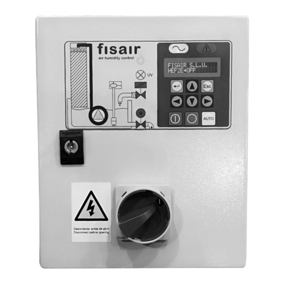
MANUAL for the basic control panel | CCB2.0 5. Hardware description Figure 3.1: CCB2.0 front cover... - Page 12 MANUAL for the basic control panel | CCB2.0 Figure 3.2: CCB2.0 open...
- Page 13 MANUAL for the basic control panel | CCB2.0 Figure 3.3: Inside cover CCB2.0 (standard)
- Page 14 MANUAL for the basic control panel | CCB2.0 Figure 3.4: Inside cover CCB2.0 (optional data bus and conductivity cards. IP connection)
- Page 15 MANUAL for the basic control panel | CCB2.0 Figure 3.4: Inside cover CCB2.0 (optional data bus and conductivity cards. RTU connection)
- Page 16 MANUAL for the basic control panel | CCB2.0 LED / Key/ Component Description, Function and Article Code Disconnector switch (I1) for cutting and isolating the supply voltage; possibility of locking by padlock (not supplied) Art. Cod.: 64300129 HMI. Command and display interface SEF-027.1 Art.
- Page 17 MANUAL for the basic control panel | CCB2.0 LED / Key/ Component Ref. Description, Function and Article Code Float switch status LED: Yellow. Indicates level below minimum Green. Indicates operating level Red. Indicates maximum water level ...
- Page 18 MANUAL for the basic control panel | CCB2.0 LED / Key / Component Ref. Description, Function and Article Code RL8 relay for motor-valve drain/emptying Code Art: 64130018 Fuse F2 for auxiliary power protection Art. Cod.: 64600012 Fuse F3 to protect the water supply solenoid valve Art.
- Page 19 MANUAL for the basic control panel | CCB2.0 LED / Key / Component Ref. Description, Function and Article Code Battery 3V CR2032 Art. Cod.: 69101000 40 pins Flat cable connector 40 pins. Between SEF- 28.1 and SEF-025.1 CCB2.0 rating plate. For ubication see chapter 4.
-
Page 20: Connections
MANUAL for the basic control panel | CCB2.0 6. Connections 1) Connect the standard accessories to the SEF-028.1 card according to Figure 4.1. Figure 4.1: SEF-028.1 card Type of Max. Power Symbol Connection Description connection Max. Voltage Optional. +24VDC J12*... - Page 21 MANUAL for the basic control panel | CCB2.0 Type of Max. Power Symbol Connection Description connection Max. Voltage UV lamp operating sensor (if Optional. J18** Not powered applicable) Forced drainage remote signal: The rest of the signals are ignored, Optional.
- Page 22 When cable length > 15 m → It can happen that the resistivity of the cable or an excess of noise in the line, produces a potential drop in it. In these cases, a high sensitivity relay must be inserted, close to the CCB2.0 panel, which is actuated externally. Example: Connection at J21 (H1):...
- Page 23 MANUAL for the basic control panel | CCB2.0 2) (Optional, only for CCB2.0+ Conductivity control) Connect the conductivity probe to the SEF-026 card and the cables according to the indicated colours (earth to J3, either of the two interlocks): Figure 4.2: SEF-026 Card 3) (Optional, Modbus RTU communication) Connect the 3 cables identified with X, A and B on the SEF-030.1 card.
- Page 24 MANUAL for the basic control panel | CCB2.0 4) With the disconnector in position 0, connect the appropriate mains supply for each case to the supply terminals X1: 3-phase line connection Single-phase line connection Proper wiring prevents electrical noise. Electrical noise can produce undesirable effects on electronic control circuits, which affects controllability.
-
Page 25: Supervision
MANUAL for the basic control panel | CCB2.0 7. Supervision START: This is the main screen that appears once the equipment is powered by the disconnector (I1) which shows the following information through 2 screens that alternate continuously: Screen 1: ❖... - Page 26 MANUAL for the basic control panel | CCB2.0 AUTO: Select Automatic mode (AUTO) from the command and display interface to enter that mode. The following information is shown on the Display through 2 screens that alternate continuously. Screen 1: ❖ Name of the Company: FISAIR, S.L.U.
-
Page 27: Configuration
8. Configuration Configure the basic control panel according to your air handling needs as part of the process incorporating the Fisair Evaporative Humidifier. Pay special attention to the water supply quality, the application hygiene requirements and the required work cycles. -
Page 28: Standard Emptying
MANUAL for the basic control panel | CCB2.0 8.1.2. Standard emptying: Complete emptying of the basin depends on the following Timers*: ❖ Timer T05 (Min. NEVER / Max. 24h) While the equipment is running, it is fully emptied periodically according to the time value set in T05. -
Page 29: Stages Conf
MANUAL for the basic control panel | CCB2.0 8.3. Stages Conf. Not available in the Basic Control Panel 2.0 (CCB2.0). Staged regulation is only available in the Stages Control Panel 2.0 (CCE2.0). Note 1: This setting must be set to "NO" for the recirculation pump to start. -
Page 30: Bus Configuration
MANUAL for the basic control panel | CCB2.0 8.7. Bus configuration You can configure 3 types of data bus (Modbus RTU, Modbus TCP / IP and BACnet). Depending on the type, its configuration protocol varies: 8.7.1. MODBUS: TCP/IP y RTU Pay attention to the following screens that the Display shows regarding this type of communication: ❖... - Page 31 MANUAL for the basic control panel | CCB2.0 Mapping for MODBUS communication protocols: Write: The following table shows the write function of each communication address: Address Description Writing 1010 Write position disconnector switch I1 0→Off, 1→Manual, 2→Auto (Subject to interlocking function in J21)
- Page 32 MANUAL for the basic control panel | CCB2.0 Read: The following table shows the read function of each communication address: Address Description Reading 2010 Status read On/Off Off→0, On→1 2012 Read conductivity value 0-1999 µS/cm* 2014 Read temperature value ºC...
- Page 33 MANUAL for the basic control panel | CCB2.0 Address Description Reading 2132 Read pump status J11 0→not operating (green led [16] Off) 1→Operating (green [16] 2→Pump fault (red led [16] On) 2134 Motor pump circuit breaker status 0→Circuit breaker fault 1→Circuit breaker correct...
-
Page 34: Bacnet/Ip
MANUAL for the basic control panel | CCB2.0 8.7.2. BACnet/IP: Pay attention to the following screens that the Display shows regarding this type of communication: ❖ BACNET UDP Port: Select the address of the Bacnet UDP Port. By default it is 47808. - Page 35 MANUAL for the basic control panel | CCB2.0 Object Description Writing range (increase) Factory setting SETPOINT µS* Write conductivity 0-1999µS/cm*(increase 300 µS/cm (Analog_Output:9)=1012 Set-Point 1µS/cm) SET Timer 1* Write Timer T01 30-1000s(increase 15s) (Analog_Output:1)=1030 SET Timer 2* Write Timer T02...
- Page 36 MANUAL for the basic control panel | CCB2.0 Object Description Reading GET STATUS J25 Read equipment live J25 0→not live (yellow led [3]Off) (Analog_Input:4)=2116 1→live (yellow led [3]On) GET STATUS J23 Read general equipment 0→no equipment failure(red led [4] (Analog_Input:5)= 2118...
- Page 37 MANUAL for the basic control panel | CCB2.0 Object Description Reading GET STATUS J11 Read pump status J11 0→not operating (green led [16] Off) (Analog_Input:12) =2132 1→Operating (green led [16] On) 2→Pump fault (red led [16] On) GET STATUS BREAKER Motor pump circuit breaker 0→Circuit breaker fault...
-
Page 38: Language
MANUAL for the basic control panel | CCB2.0 8.8. Language Select the language you want from the Display: ❖ Español ❖ English ❖ Deutsch ❖ Francais 8.9. Date Set the exact date and time by entering the data shown on the following screens: ❖... -
Page 39: Settings
MANUAL for the basic control panel | CCB2.0 9. Settings The desired values for the different parameters to be adjusted are configured in this section. The conductivity set-point and the different Timers are configured. Each parameter has a range of values it can be set to. -
Page 40: Timer T02 (Ex Sw1 Cd)
MANUAL for the basic control panel | CCB2.0 9.3. TIMER T02 (ex SW1 CD) Enter the time between partial emptying of the basin with conductivity control. The Timer range is from 1 min to 15 min. The factory set value is 5 min. -
Page 41: Timer T06 (Ex Sw3 Cd)
MANUAL for the basic control panel | CCB2.0 9.7. TIMER T06 (ex SW3 CD) Enter the delay before complete emptying after the equipment has been turned off. The Timer range is from 0 h to 24 h. The factory set value is 1 h. -
Page 42: Calibration
MANUAL for the basic control panel | CCB2.0 10. Calibration Calibration is recommended every 12 months. This is done as follows: Immerse the probe tip in the HI 7061 Cleaning Solution (item code 69510002) for at least one hour. If thorough cleaning is required, wipe the metal tips with very fine sandpaper or a non-abrasive brush. -
Page 43: Launching
After the pre-installation steps and all connections have been made according to the corresponding electrical diagram: (See the electrical diagram number on the ratings plate inside the CCB2.0) 1. Check the mains voltage corresponds to the CCB2.0 supply voltage according to its corresponding electrical diagram. - Page 44 MANUAL for the basic control panel | CCB2.0 Partial emptying operation (if Conductivity Control is applied): Once the SET-POINT and TIMER T07 are exceeded (the latter establishes the time the set- point has to be continuously exceeded), the emptying motor valve will open and the water in the basin will be renewed, due to the filling solenoid valve staying open (the filling solenoid valve is controlled and closes only when the maximum level is detected).
- Page 45 MANUAL for the basic control panel | CCB2.0 5. Operation: If the UV lamp is on, the LED flashes blue until the confirmation of the ignition sensor is received. It will then stop flashing and be lit continuously in blue. If the lamp is submerged, J18 must be bridged (IN1) as it works for hours.
-
Page 46: Alarms
MANUAL for the basic control panel | CCB2.0 12. Alarms List of alarms: Signal for alarm Component Description of the alarm Recommended action Internal card failure: SEF-025.1 Contact Technical Services Replace battery and/or contact RAM memory RAM memory Technical Services to reload the... -
Page 47: Declaration Of Conformity
MANUAL for the basic control panel | CCB2.0 13. Declaration of conformity 13.1. D.C. Machine... -
Page 48: Partly Completed Machinery
MANUAL for the basic control panel | CCB2.0 13.2. D.C. Partly completed machinery... -
Page 49: Warranty
MANUAL for the basic control panel | CCB2.0 14. Warranty... - Page 50 MANUAL for the basic control panel | CCB2.0...
Need help?
Do you have a question about the CCB2.0 and is the answer not in the manual?
Questions and answers