
Summary of Contents for Keba KeContact KC-S10
- Page 1 KeContact KC-S10 Phase switching device Installation manual V 1.00 Translation of the original instructions...
- Page 2 Specifications are subject to change due to further technical developments. Details presented may be subject to correction. All rights reserved. Reindlstraße 51, 4040 Linz, Austria, www.keba.com/emobility KEBA Energy Automation GmbH +43 732 7090-0, +43 732 7309-10, kecontact@keba.com For information about KEBA and our subsidiaries please look at www.keba.com.
-
Page 3: Table Of Contents
General criteria for the site selection ............... Space requirements..................Required tools....................Mounting the device..................Connections and wiring..................... Required tools....................Power supply ....................Configuration ......................Commissioning ......................Perform safety checks ..................10 Maintenance........................ 10.1 Troubleshooting ....................11 Disposal ........................© KEBA 2022... - Page 4 Power supply ....................12.3 Interfaces ......................12.4 Ambient conditions................... 12.5 Mechanical properties..................12.6 Dimensions and weight..................13 Directives, standards and regulations ..............13.1 EU Directives and Standards................14 UKCA ........................... 15 Declaration of conformity..................16 Appendix: Drilling template..................© KEBA 2022...
-
Page 5: Introduction
This symbol reminds you of the possible consequences of touching electro- statically sensitive components. Information Identifies practical tips and useful information. No information that warns about potentially dangerous or harmful functions is contained. © KEBA 2022... -
Page 6: Purpose Of The Document
The device is intended for monitoring and controlling the input voltage of a charging station for electrically powered vehicles and may only be operated in combination with a KEBA charging station. Information The device may only be operated with a charging station with software ver- sion ≥... -
Page 7: Notes On This Document
Description of the charging station Additional documentation Manuals and additional information are available on our website: www.keba.com/emobility-downloads Designation Target group ● End customer P30 operating instructions ● Electricians ● End customer P30 configuration manual x-series ● Electricians © KEBA 2022... -
Page 8: Safety Notes
● When connecting and wiring the device, ensure that the connection area is clean so that no foreign objects (pieces of wire, etc.) get inside. ● Never clean the device with aggressive solvents and cleaning agents, abrasive materials, spray water (garden hose, high-pressure cleaner, etc.) or excessive pressure. © KEBA 2022... -
Page 9: Scope Of Delivery
KC-S10 Scope of delivery Scope of delivery The following materials are included: ● 1 x M20 cable gland ● 2 x M32 cable gland ● 4 x cover for inner mounting screws © KEBA 2022... -
Page 10: System Overview
The charging process is carried out with just 1 phase. When sufficient cur- rent becomes available again, KC-S10 enables all phases to be used. Fig. 4-1: System overview ... Power supply ... Energy meter ... KC-S10 ... Charging station © KEBA 2022... -
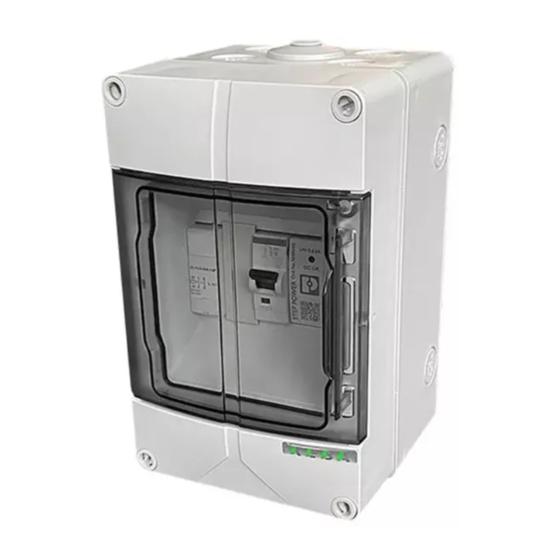
Page 11: Description
KC-S10 Description Description Front view Fig. 5-2: Front view ... Housing screws ... Housing cover ... Hinged cover Rear view Fig. 5-3: Rear view ... Knockout for M20 cable insertion ... Mounting holes opening © KEBA 2022... -
Page 12: Side View
(for power supply) ... Housing box ... Housing cover Information The positions of the knockouts for cable insertion openings are identical on the underside. Type plate The type plate is located on the lower right of the device. © KEBA 2022... - Page 13 Fig. 5-6: Example type plate ... Manufacturer ... Product designation ... Technical data ... Test report no.: ... Manufacturer's address ... Country of manufacture ... Equipment class II ... UKCA marking ... CE conformity marking © KEBA 2022...
-
Page 14: Mounting And Installation Instructions
The device was designed for indoor and outdoor use. Accordingly, it is nec- essary to ensure the correct set-up requirements and the protection of the device at the installation site. The following criteria must be taken into account when selecting a location: © KEBA 2022... -
Page 15: Space Requirements
Observe the permissible environmental conditions (see "Technical data"). Observe the internationally valid standards and comply with the nationally applicable regulations. Space requirements The device must be installed with the following clearances to the surround- ings. Fig. 6-7: Space requirement, specified in mm © KEBA 2022... -
Page 16: Required Tools
6) Offset any unevenness with washers. 7) Position the device on the wall and tighten to the wall with the four screws (max. 1.2 Nm). The device is now mounted on the wall and ready for wiring. © KEBA 2022... -
Page 17: Connections And Wiring
The supply line must be routed straight through the opening in compli- ance with the bending radii (approx. 10x cable diameter). 7.2.2 Connection example The device is connected using the three phases L1, L2 and L3, the neutral conductor N and the protective conductor PE. © KEBA 2022... - Page 18 Risk of electric shock and fire hazard! The X2.1 and X2.2 supply lines must be wired with a cable with the corre- sponding insulation for 230 V. Other lines in the housing may touch these lines. Fig. 7-8: Circuit diagram © KEBA 2022...
- Page 19 ... Wiring to floating contact X2 of the ... Terminal X1.L1 charging station ... Contactor 1K7 ... Terminal X1.N and grounding termi- nal X1.PE ... Circuit breaker 1F6 ... Power adapter 1T5 ... Terminals X2.1 and X2.2 © KEBA 2022...
-
Page 20: Configuration
2) On the "Charging Network" tab, go to the "Phase switching" menu item. 3) Switch "Dynamic switching 1-phase/3-phase charging operation" to "ON". "X2 connection status" switches to "Active" here. 4) Select "Communication channel" in the dropdown menu. © KEBA 2022... -
Page 21: Commissioning
RCD (FI) triggering current, triggering time, etc.) are to be performed. ● The measurement devices must comply with the national regulations! ● The measurement results are to be documented. A test report is to be created and saved before the check. © KEBA 2022... -
Page 22: Maintenance
Maintenance KC-S10 Maintenance No further maintenance work is necessary. The device is maintenance free. 10.1 Troubleshooting Further information (e.g. operating and configuration instructions) and con- tact details are available on our website: www.keba.com/emobility-downloads © KEBA 2022... -
Page 23: Disposal
● The materials are recyclable in accordance with their labeling. You can make an important contribution to protecting our envi- ronment by reusing, renewing and recycling materials and old appliances. © KEBA 2022... -
Page 24: Technical Data
On a wall Ambient temperature: -5 °C to 50 °C Ambient temperature 24h: 35 °C Storage temperature: -30 °C to +80 °C Max. relative humidity: ● At 25 °C: 95% non-condensing ● At 40 °C: 50% non-condensing © KEBA 2022... -
Page 25: Mechanical Properties
Polycarbonate, blue transparent ● Seal: Polyurethane ● Housing screws: Polyamide, glass fiber reinforced Flame retardance: UL94 V-2 12.6 Dimensions and weight Height / width / depth: 200 mm / 125 mm / 122 mm Weight: approx. 1.1 kg © KEBA 2022... -
Page 26: Directives, Standards And Regulations
13.1 EU Directives and Standards 2014/35/EU Low-voltage Directive 2014/30/EU Electromagnetic Compatibility Directive Directive on the restriction of the use of cer- 2011/65/EU tain hazardous substances (RoHS) Directive for waste electrical and electronic 2012/19/EU equipment (WEEE) © KEBA 2022... -
Page 27: Ukca
Produkte erforderlich ist, die in Großbritannien (England, Wales und Schottland) auf den Markt gebracht werden. Authorised representative is: KEBA Ltd. Aston Court Frederick Place Kingsmead Business Park High Wycombe HP11 1JU Authorised representative to compile the technical file is KEBA Ltd. © KEBA 2022... -
Page 28: Declaration Of Conformity
Declaration of conformity KC-S10 Declaration of conformity The declaration of conformity of this product is available on request from KEBA. © KEBA 2022... -
Page 29: Appendix: Drilling Template
KC-S10 Appendix: Drilling template Appendix: Drilling template © KEBA 2022... - Page 30 KC-S10 © KEBA 2022...
- Page 32 KEBA Energy Automation GmbH Reindlstraße 51 4040 Linz / Austria www.keba.com...
Need help?
Do you have a question about the KeContact KC-S10 and is the answer not in the manual?
Questions and answers