Table of Contents
Advertisement
Quick Links
Translation of the original installation and maintenance
DM.ZS-EN_23-09
instructions
DYNAMIC MODULES WITH RACK AND PINION DRIVES
Read the installation and maintenance instructions before carrying out any work!
LINE TECH AG | Europastrasse 19 | CH-8152 Glattbrugg
Tel +41 43 211 68 68 | info@linetech.ch | www.linetech.ch
Advertisement
Table of Contents

Summary of Contents for Line Tech DM2.ZR
- Page 1 Translation of the original installation and maintenance DM.ZS-EN_23-09 instructions DYNAMIC MODULES WITH RACK AND PINION DRIVES Read the installation and maintenance instructions before carrying out any work! LINE TECH AG | Europastrasse 19 | CH-8152 Glattbrugg Tel +41 43 211 68 68 | info@linetech.ch | www.linetech.ch...
-
Page 2: Table Of Contents
Product description ..................... Type plate ........................4 Transport ......................23 Safety.......................... Transportation with a forklift truck ................Transport with the crane ..................... Transport inspection and scope of delivery ..............Storage ........................5 Assembly......................26 Safety.......................... 2 / 68 Line Tech AG... - Page 3 Exploded drawing and parts list .................. General technical data ....................Dimensions ......................... Torques and load ratings .................... Permissible speeds..................... Tightening torques for screws..................10 Links ........................62 11 Declaration of Incorporation................63 Index ........................66 Line Tech AG 3 / 68...
-
Page 4: General Information
Figures contained in these assembly instructions are provided for basic understanding and may vary from the actual version of the dynamic module. Loss of the assembly instructions If the assembly instructions are lost, request a replacement set immediately. Contact details Legal notice (See reverse side) . 4 / 68 Line Tech AG... -
Page 5: Notes On Use
Example: see chapter Information about these assembly instructions [} 4]. Figures All figures and drawings in these assembly instructions are intended for general illustration purposes. They may vary from the actual design of the dynamic module. Line Tech AG 5 / 68... -
Page 6: Structure Of The Warnings
A warning assigned to this danger level indicates an imminently dangerous situation. If the dangerous situation is not avoided, it will result in death or serious injury. Follow the instructions in this warning to avoid the risk of death or serious injury to persons. 6 / 68 Line Tech AG... - Page 7 4 Notes on prevention A warning assigned to this danger level indicates possible damage to property. If the situation is not avoided, property damage may occur. Follow the instructions in this warning to avoid damage to property. Line Tech AG 7 / 68...
-
Page 8: Symbols Used
Symbols used Warnings in these assembly instructions are also marked with warning symbols. Warning symbols The following warning symbols are used in these assembly instructions: Symbol Meaning General warning Warning of electrical voltage 8 / 68 Line Tech AG... -
Page 9: Disclaimer
The date of issue of these assembly instructions applies. We reserve the right to make technical changes to the dynamic module within the scope of further development in order to improve its performance features and safety. Line Tech AG 9 / 68... - Page 10 – Non-compliance with the information and instructions in these assembly instructions – Work performed on or with the dynamic module by unqualified or unauthorized personnel – Installation of non-original spare parts – Unauthorized conversions without written approval from the manufacturer 10 / 68 Line Tech AG...
-
Page 11: Spare Parts
In case of modifications or significant repairs carried out by the operator or third parties without the written consent of the manufacturer or sales partner, the warranty claim will be completely invalidated. Line Tech AG 11 / 68... -
Page 12: Customer Service And Product Monitoring
– Work instructions issued by the operating company – Safety data sheets for auxiliary and operating materials – Local accident prevention regulations and regional regulations at the operating site of the dynamic module – Data sheets for the installed components 12 / 68 Line Tech AG... -
Page 13: Safety
– The dynamic module is operated outside the limits specified in Technical data [} 49]. – Modifications are made to the dynamic module. – Safety devices are disabled. – The dynamic module is used in an explosion-protected area. Line Tech AG 13 / 68... -
Page 14: Responsibilities Of The Operating Company
Perfect working order In order to keep the dynamic module in perfect working order at all times, the operating company must ensure that the maintenance intervals specified in these assembly instructions are observed. 14 / 68 Line Tech AG... -
Page 15: Personnel Requirements
The following personal protective equipment must be worn depending on the work to be carried out: Line Tech AG 15 / 68... - Page 16 Protective goggles are used to protect the eyes from flying small parts, dust or compressed air. NOTE External visitors or employees from other departments must also wear personal protective equipment when entering the work area. 16 / 68 Line Tech AG...
-
Page 17: Residual Risks
Dirt and objects lying around present sources of slipping and tripping: – Always keep the work area clean. – Remove objects that are no longer required. – Mark tripping hazards with yellow and black marking tape. Line Tech AG 17 / 68... -
Page 18: Hazards Due To Noise
Replaced machine parts may be contaminated with grease and oil, for example, and therefore contain toxic substances. They must not be released into the environment. They must be disposed of by a specialist disposal company in accordance with local regulations. 18 / 68 Line Tech AG... -
Page 19: Structure And Function
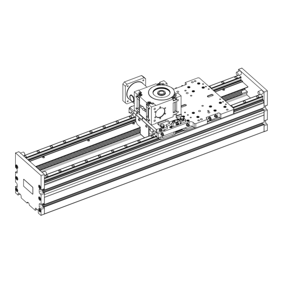
Cover Toothed rack Guide rail Gearbox Carriage Buffer Base profile End plate Base profile Carriage Toothed rack Linear rail guide Gearbox mounting plate Gearbox Drive and lubrication pinion Line Tech AG 19 / 68... -
Page 20: Product Description
The selected design results in very high performance with highly compact dimensions. The following load ratings are achieved: Dynamic module Dimensions Load ratings Type W x H [mm] [kN] [kN] DM2.ZR 180 x 188 162.0 116.3 DM3.ZR 220 x 231 311.5 208.8 20 / 68 Line Tech AG... -
Page 21: Product Description
The selected design results in very high performance with highly compact dimensions. The following load ratings are achieved: Dynamic module Dimensions Load ratings Type W x H [mm] [kN] [kN] DM2.ZS 180 x 188 192.6 131.3 DM3.ZS 220 x 241 311.5 208.8 Line Tech AG 21 / 68... -
Page 22: Type Plate
– Serial No. = serial number (3) – Date = manufacturing date; calendar week/year (4) – Manufacturer address (5) NOTE If problems occur with the dynamic module, provide the manufacturer or sales partner with the information on the type plate. 22 / 68 Line Tech AG... -
Page 23: Transport
4 Do not expose the parts to be transported to hard shocks during transportation. 4 Make sure there is sufficient clearance during transportation. 4 Always provide support for dynamic modules longer than 700 mm during transportation. 4 Be careful when lifting and setting the unit(s) down. Line Tech AG 23 / 68... -
Page 24: Transportation With A Forklift Truck
Refer to the delivery document for the scope of delivery. The scope of delivery of the product includes: – Dynamic module according to the order confirmation – Assembly instructions – Additional and special accessories according to the order 24 / 68 Line Tech AG... -
Page 25: Storage
– Store in a dry and dust-free place. – Do not expose to aggressive media. – Protect it from sunlight. – Avoid mechanical shocks. – Store dynamic modules in a box that is well padded. Line Tech AG 25 / 68... -
Page 26: Assembly
4 Do not stand under suspended loads. 4 Observe environmental protection instructions. If environmentally hazardous substances are accidentally released into the environment, take appropriate measures immediately. In case of doubt, notify the responsible local authority of the damage. 26 / 68 Line Tech AG... -
Page 27: Assembly Types
» Straightness 0.2 mm/1000 mm Installation position The linear units are installed horizontally (as shown) or overhead as standard. If your application requires a vertical or lateral installation position, please contact our Technical Sales department in advance. Line Tech AG 27 / 68... -
Page 28: Condition On Delivery
5 | Assembly DYNAMIC MODULES WITH RACK AND PINION DRIVES Condition on delivery LINE TECH dynamic modules are available in various delivery conditions. The following delivery conditions are possible: [A] Gearbox mounted at rear [B] Gearbox mounted at front 28 / 68... -
Page 29: Gearbox Selection
The dynamic modules with a rack and pinion drive can each be equipped with an angular gearbox with motor flange (1) or with an angular gearbox with a drive shaft (2): DM2.ZS… Standard gearbox DM3.ZS… Standard gearbox Line Tech AG 29 / 68... -
Page 30: Fastening The Dynamic Module
4 Only fasten or support dynamic modules on the base profile and not on the end plates. 5.5.2 Fastening the dynamic module with clamps Overview DM2 & DM3 ±0.1 Nominal size Dimensions [mm] (DIN912) DM2... M8x50 DM3... M8x60 Recommended screw length 30 / 68 Line Tech AG... - Page 31 DYNAMIC MODULES WITH RACK AND PINION DRIVES Assembly | 5 Clamps Recommended number of clamps: 3 pieces per meter and side The clamps can be ordered from LINE TECH AG according to the following table. Nomin- Dimensions [mm] Weight Art. No.
-
Page 32: Fastening The Dynamic Module With Sliding Blocks
The type of sliding block to be used depends on the groove width: Dimensions [mm] Material Groove width a (thread) Groove 6 M4/M5/M6 Steel Groove 10 M4/M5/M6/M8 Steel Groove 14 Steel Assembly a) Push the sliding blocks into the corresponding groove. 32 / 68 Line Tech AG... -
Page 33: Installing The Motor And Gearbox
4 Work on the electrical equipment must only be carried out by qualified electricians. 4 De-energize the dynamic module before carrying out any work (disconnect the power plug). NOTE Observe the information in the manufacturer's instructions regarding the motors and gearboxes to be installed. Line Tech AG 33 / 68... -
Page 34: Operation
4 Never disable safety equipment during operation. 4 Make sure the work area is tidy and clean! Loose components and tools lying on top of each other or lying around may cause accidents. 34 / 68 Line Tech AG... -
Page 35: Operating Conditions
For applications in special operating conditions, such as moisture, dirt, dust (fiberglass and wood), aggressive atmosphere, extreme climatic conditions and/or strong temperature fluctuations, short stroke and others, contact LINE TECH AG before commissioning. The specified maximum values refer to one domain. If several requirements are combined (temperature/speed/load), this must be taken into consideration in the design. -
Page 36: Maintenance
4 If components have been removed or adjusted, ensure correct assembly, reinstall all fastening elements and observe the screw tightening torques. 4 Observe the specified maintenance intervals. 4 Observe environmental protection instructions. 36 / 68 Line Tech AG... -
Page 37: Repairs
Keep a maintenance log as verification that the required maintenance work has been carried out. NOTE Verification that the required maintenance work has been carried out is a mandatory requirement for claiming any warranty services. Contact the manufacturer if there are any doubts. Line Tech AG 37 / 68... -
Page 38: Maintenance Plan
Visually check that externally attached fasteners, electrical cables and plug connections are in perfect working order. If changes occur that put the safety of personnel and systems at risk, immediately shut down the dynamic module. 38 / 68 Line Tech AG... -
Page 39: Lubricating The Dynamic Module
Move the unit to both end positions at 50 mm/s. e) Another stroke with grease gun "01.103" [0.6cm3] per carriage. f) Move the unit to both end positions at 50 mm/s. g) Remove excess grease with an oiled cleaning cloth. Line Tech AG 39 / 68... - Page 40 Lubricants NOTE The modules must only be lubricated with grease. LINE TECH AG recommends specific greases as shown in the table below. When using other greases (third-party products), their compatibility with the standard grease must first be checked. Observe the safety data sheet.
- Page 41 All bearings are lubricated for life and do not require any maintenance. NOTE After a standstill of longer than 1 year, relubricate the system until the fresh grease emerges at the lubrication points. The lubricant age should never exceed 2 years in the entire system. Line Tech AG 41 / 68...
- Page 42 24 operating hours. This lubrication quantity can be distributed over several intervals. The lubrication quantity must reach the specified value within 24 hours. 42 / 68 Line Tech AG...
- Page 43 Version left (A) / outside (C) / inside (D) Version right (B) / inside (D) / outside (C) Lubrication point Object R ** B + C * E + F * * Carriage ** Toothed rack Line Tech AG 43 / 68...
- Page 44 Version left (A) / outside (C) / inside (D) Version right (B) / inside (D) / outside (C) Lubrication point Object R ** B + C * E + F * * Carriage ** Toothed rack 44 / 68 Line Tech AG...
-
Page 45: Setting The Toothed Rack Play
Check the tooth flank play by moving the carriage back and forth. Module Tooth Fastening nut Adjusting screw Lock nut flank play [mm] WAF [mm] M [Nm] Allen M [Nm] M [Nm] screw [mm] [mm] DM2.ZS 0.02-0.04 DM3.ZS 0.02-0.04 Line Tech AG 45 / 68... -
Page 46: Measures After Completing The Maintenance Work
There is a risk of injury to personnel located in or reaching into the danger zone if the device is switched on again. 4 Before switching the system back on, make sure that there are no personnel in the danger zone or reaching into the danger zone. 46 / 68 Line Tech AG... -
Page 47: Disassembly And Disposal
Decommissioning and disassembly To decommission the dynamic module: a) Switch off the power supply to the entire system and disconnect it from the power supply. b) If necessary, disconnect the pneumatic connections. Line Tech AG 47 / 68... -
Page 48: Disposal
Pretreat and dispose of the components according to the following table: Components Pretreatment Disposal Mechanical components Clean Scrap Greases Remove, clean See the safety data sheet Oils Drain, pump out See the safety data sheet 48 / 68 Line Tech AG... -
Page 49: Technical Data
DYNAMIC MODULES WITH RACK AND PINION DRIVES Technical data | 9 Technical data Exploded drawing and parts list Standard version Basic structure End plate Carriage Gearbox unit Line Tech AG 49 / 68... -
Page 50: General Technical Data
Depending on the load and gearbox ratio ➙ see "Permissible speed" diagrams, chapter Permissible speeds [} 58] Larger strokes on request Higher speeds according on request Without gearbox idling torque, this depends on its reduction ratio 50 / 68 Line Tech AG... -
Page 51: Dimensions
34.5 34.5 1/2 stroke 1/2 stroke Toothed rack assembly side Nominal size Dimensions Designation Weight (excluding gearbox) [mm] [mm] [kg] DM2.ZS…A/B… Stroke + 404 L – 30 21.39 kg + 3.06 kg/100 mm stroke Line Tech AG 51 / 68... - Page 52 1/2 stroke 34.5 1/2 stroke 34.5 min.15 Toothed rack assembly side Nominal size Dimensions Designation Weight (excluding gearbox) [mm] [mm] [kg] DM2.ZS...C/D… Stroke + 754 L – 30 44.55 kg + 3.06 kg/100 mm stroke 52 / 68 Line Tech AG...
- Page 53 DYNAMIC MODULES WITH RACK AND PINION DRIVES Technical data | 9 Carriage plate dimensions DM2.ZS 12.5 Montagefläche 12x A) Getriebe ø 6 F8 Tiefe 3.3 16.5 ø 9 ø 15 4x B) 4x C) 12.5 ø 8 F8 2x D) Line Tech AG 53 / 68...
- Page 54 - 1 carriage with gearbox on left or with gearbox on right 1/2 stroke 1/2 stroke Toothed rack assembly side Nominal size Dimensions Designation Weight (excluding gearbox) [mm] [mm] [kg] DM3.ZS…A/B… Stroke + 534 L – 40 55.6 kg + 5.0 kg/100 mm stroke 54 / 68 Line Tech AG...
- Page 55 1/2 stroke 1/2 stroke min. 17 Toothed rack assembly side Nominal size Dimensions Designation Weight (excluding gearbox) [mm] [mm] [kg] DM3.ZS…C/D... Stroke + 1001 L – 40 95.1 kg + 5.0 kg/100 mm stroke Line Tech AG 55 / 68...
- Page 56 9 | Technical data DYNAMIC MODULES WITH RACK AND PINION DRIVES Carriage plate dimensions DM3.ZS 16x A) Montagefläche Getriebe Tiefe 4 ø 6 F8 ø 9 8x C) 8x B) ø 15 56 / 68 Line Tech AG...
-
Page 57: Torques And Load Ratings
50 km. If comparative values need to be calculated for a stroke of 100 km, divide the values for Mx 50, My 50, Mz 50 and C 50 by a factor of 1.26. Line Tech AG 57 / 68... -
Page 58: Permissible Speeds
[min ] / M [Nm] where [–] = Gearbox ratio [rpm = Input speed [Nm] = Input torque = Max. axial load [m/min] = Max. speed Permissible speed DM2.ZS... with angular gearbox 58 / 68 Line Tech AG... - Page 59 DYNAMIC MODULES WITH RACK AND PINION DRIVES Technical data | 9 Permissible speed DM3.ZS... with angular gearbox Line Tech AG 59 / 68...
- Page 60 9 | Technical data DYNAMIC MODULES WITH RACK AND PINION DRIVES 60 / 68 Line Tech AG...
-
Page 61: Tightening Torques For Screws
Technical data | 9 Tightening torques for screws Screws of strength class 8.8 are used as standard. If other screws are used, they are specially marked. The tightening torques recommended by LINE TECH AG are defined in the following table. Tightening torques M [Nm] Friction factor for screws µ... -
Page 62: Links
DYNAMIC MODULES WITH RACK AND PINION DRIVES Links Links to the detailed digital MAWA Link to PDF catalog (German) DM.ZS (German) https://www.linetech.ch/qr/qr0008 https://www.linetech.ch/qr/qr0010 Links to the detailed digital MAWA Link to PDF catalog (English) DM.ZS (English) https://www.linetech.ch/qr/qr0011 https://www.linetech.ch/qr/qr0009 62 / 68 Line Tech AG... -
Page 63: Declaration Of Incorporation
DYNAMIC MODULES WITH RACK AND PINION DRIVES Declaration of Incorporation | 11 Declaration of Incorporation Declaration of Incorporation according to EC Machinery Directive 2006/42/EC, Annex II 1. B (Translation of original Declaration of Incorporation) Manufacturer Line Tech AG Europastrasse 19 CH-8152 Glattbrugg Module name Dynamic module (DM) Type designation according to type plate (see Type plate [} 22]) - Page 64 Applied harmonized standards The machine complies with the safety requirements set forth in the following harmonized standards: DIN EN ISO 12100:03/2011: Safety of machinery - General principles for design - Risk assessment and risk reduction 64 / 68 Line Tech AG...
- Page 65 The product may not be commissioned until it has been established that the machine in which the aforementioned product is installed complies with all the essential requirements of the Machinery Directive. Michael Bozenhardt (Head of Technology) LINE TECH AG Europastrasse 19 CH-8152 Glattbrugg Glattbrugg, September 2023 Line Tech AG...
-
Page 66: Index
Product description 20, 21 Protective equipment 15 Protective goggles 16 Greases 18 Qualification 15 Qualified personnel 15 Hearing protection 16, 18 Repairs 37 Requirements 4 Instructions 14 Intended use 13 Item to be transported 24 66 / 68 Line Tech AG... - Page 67 Tooth flank play 45 Toothed rack play 45 Type plate 22 Warning symbols 8 Electric current 8 Environmental pollution 8 Suspended load 8 Warranty claims 11 Warranty conditions 11 Work clothing 16 Work clothing; appropriate 16 Line Tech AG 67 / 68...
- Page 68 Linear movements form the backbone of modern industrial production systems. LINE TECH AG has been providing linear technology solutions every day for over 25 years. LINE TECH AG is distinguished by a comprehensive range of components, linear and positioning systems coupled with the technical expertise of our employees.
Need help?
Do you have a question about the DM2.ZR and is the answer not in the manual?
Questions and answers