Table of Contents
Advertisement
Quick Links
Advertisement
Table of Contents

Related Manuals for EG Aircraft MX2 50CC Giant Scale Aerobatic Aircraft


Summary of Contents for EG Aircraft MX2 50CC Giant Scale Aerobatic Aircraft
- Page 1 MX2 50CC Giant Scale Aerobatic Aircraft...
-
Page 2: Giant Scale Aerobatic Aircraft
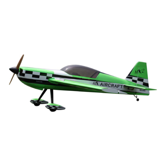
0 B 0 B 0 B M X2 50CC 1 B 1 B Giant Scale Aerobatic Aircraft S pecifications: U U U Scale:30% Wing Span:89”2260mm Length:Including spinner82”(2080mm) (94.6 dm²) Wing Area: 1466 in² (7.3-8.2kg) Flying Weight: 16 to 18 lbs Spinner: 3.5”(89mm)... -
Page 3: Included Features
A QUICK WORD ABOUT SAFETY AND RADIO CONTROL FLYING MODELS U U U With radio control aircraft, like any hobby or sport, there are certain risks. The operator of these models is responsible for these risks. If misused or abused, you may cause serious bodily injury and/or damage to property. -
Page 4: Rudder Installation
We have found this to be helpful with models intended for higher speed flight or models with unusually large hinge gaps. EG aircraft utilize a very tight double beveled hinge line and do not normally require this step. Sealing the hinge gaps is therefore left as an option for the modeler. - Page 5 2. Mix up some 30 minute epoxy and coat the inside of the slots and the center of the control horns. Hint: a scrap piece of 1/16” ply, toothpick, or old hobby blade can be used to coat the inside of the rudder slots. Slide the control horns in place and make sure they are centered perfectly by using a ruler to measure between the pivot holes and the hinge line.
-
Page 6: L Anding Gear Assembly
7. Make sure the rudder is fully seated so that the hinge gap is minimal while still allowing full deflection of the rudder. When satisfied, use some masking tape to hold the rudder in place along the bottom and counterbalance. After the epoxy has cured, remove the masking tape and check for proper operation. - Page 7 3.Install the main wheel axles to the composite landing gear and tighten the nylon-insert lock nut. Install one wheel collar onto the axle. Use a second wheel collar as a guide to leave a gap on the inboard of the axle.
- Page 8 4. Fit the wheel pant in place and install using the two supplied screws. Use thread-lock to secure the screws in place. Repeat the above steps for the other main gear. 5. Begin the tail wheel assembly by installing the shaft bushing and lock nut into the large hole at the rear of the tail wheel bracket.
- Page 9 6. Center the tail wheel bracket on the rear of the fuselage and screw in place using three of the supplied wood screws. Remove the screws and harden the holes with a drop of thin CA. Allow the CA to cure and then permanently install the tail wheel bracket.
- Page 10 1. The ARF is supplied with a high quality set of pull-pull cables and ball-links. Servo openings are provided in the aft section of the fuselage below the horizontal stabilizer for those builders using an engine heavier than a typical 50 cc engine or needing to move weight aft. The below instructions are for the pull-pull cable option.
- Page 11 5. Use your radio system to center the rudder servo and attach either the supplied arm or an appropriate arm for your servo. Thread one of the ball links about half way onto one of the threaded couplers. Feed the loose end of one of the cables through a brass tube and then through the threaded coupler. Holding the rudder centered, adjust the cable length as tight as possible while checking the ball link position over the servo arm.
- Page 12 thread-lock is also highly recommended for the engine bolts. The pictures below show the DA50 engine installation. 3. Mount the ignition module according to the manufacturer’s instructions. The best place to mount it is on the side or top of the engine box. Secure the pickup lead and ignition wires with zip ties so that they do not vibrate or touch any hot part of the engine or exhaust.
- Page 13 Optional servo location 100 cc servo location optional servo location 6. The fuel tank is preassembled. Complete the installation in the fuselage using zip ties or velcro straps to hold the tank in position. Connect a fuel line between the tank and carb, a fuel line between the tank vent and the bottom of the fuselage, and a fill line to a fueling port which can be mounted on the fuselage side opposite your ignition switch.
-
Page 14: C Owling Installation
C OWLING INSTALLATION: 1. Fit the cowling in place and make any cutouts necessary to clear your engine and exhaust components. Trial fit and trim as necessary being careful and accurate. Be sure to allow enough air exit area in the bottom of the cowling to provide adequate air flow over the engine. - Page 15 3. Use your radio to set the servo center position and install the large control horn onto the servo. Assemble the control rod and ball links and adjust the control linkage for proper geometry. When satisfied, screw the ball link to the servo arm. The servo arm should be as close to perpendicular to the control rod as possible while the elevator is at neutral.
- Page 16 3. Use your radio to set the centers of each servo and then assemble and adjust the length of each control rod. The servo arm should be as close to perpendicular to the control rod as possible while the elevator is at neutral.
- Page 17 F INAL RADIO SYSTEM INSTALLATION: 1. Whether you 72 MHz systems or the newer 2.4 GHz systems, proper radio installation and care is vital to the safe and reliable operation of your aircraft. Follow the manufacturer’s instruction for installation guidance of receivers and batteries paying attention to factors such as vibration isolation, adequate cooling, and clearances.
- Page 18 1. Most state of the art aerobatic aircraft allow for a wide margin for balancing depending on what level of precision or freestyle the pilot prefers. To perform properly without being too pitch sensitive, you must not go too aft on the CG. EG recommends an initial CG setting of 6.0 – 7.0 inches behind the leading edge of the wing at the root.
Need help?
Do you have a question about the MX2 50CC Giant Scale Aerobatic Aircraft and is the answer not in the manual?
Questions and answers