Table of Contents
Advertisement
Quick Links
Advertisement
Table of Contents

Summary of Contents for Axiom megagen x48
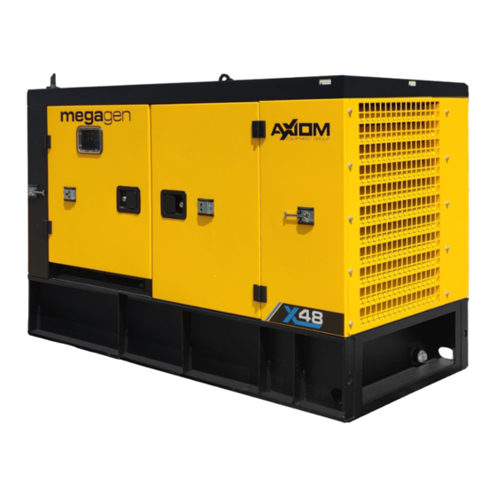
- Page 1 ELECTRIC POWER GENERATOR MODEL x48 OPERATOR'S MANUAL...
- Page 2 megagen LIMITED WARRANTY GENERAL TERMS AND CONDITIONS The product warranty is subject to the manufacturer’s general terms and conditions of sale. Acknowledgment of the warranty depends on the strict and proven observance of the operating instructions in this operator’s manual and application of the correct mechanical and electro-technical practices. The warranty will not be valid in the event of: •...
- Page 3 megagen ELECTRIC POWER GENERATOR WARRANTY REGISTRATION FORM & INSPECTION REPORT WARRANTY REGISTRATION delivery. __________________________ ___________________________ Address __________________________________ Address ________________________________ _______________________ _____________________ ___________________ ___________________________ _____________________ _________________________ _______________________ Delivery Date ______________________________ DEALER INSPECTION REPORT SAFETY ______ ______ ______ ______ ______ ______ ______ ______ ______ Date _______________________________...
- Page 4 SERIAL NUMBER LOCATIONS megagen Always give your dealer the serial number of your x48 generator when ordering parts or requesting service or other information. The serial number plates are located where indicated. Please mark the number in the space provided for easy reference.
-
Page 5: Table Of Contents
TABLE OF CONTENTS SECTION DESCRIPTION PAGE Introduction ............7 Safety ..............8 General Safety ............9 9 Equipment Safety Guidelines .......10 Safety Training ............11 Safety Signs ............11 Storage Safety ............11 Preparation Safety ..........12 Installation Safety ..........12 Maintenance Safety ..........13 Lock-Out Tag-Out Safety........13 2.10 Battery Safety ............13 2.11... -
Page 7: Introduction
INTRODUCTION megagen Congratulations on your choice of a megagen x48 generator and welcome to 's quality line of gener- ating equipment. This equipment is designed and manufactured to meet the needs of a discriminating buyer in the industry for generation of electric power. -
Page 8: Safety
SAFETY SAFETY ALERT SYMBOL The Safety Alert symbol identifies This Safety Alert symbol means important safety messages on your ATTENTION! BECOME ALERT! megagen generator and in the YOUR SAFETY IS INVOLVED! manual. When you see this symbol, be alert to the possibility of personal injury or death. -
Page 9: General Safety
SAFETY 2.1 GENERAL SAFETY YOU are responsible for the SAFE operation and megagen generator. YOU maintenance of your Operator's Manual and all safe- must ensure that you and anyone else who is going to ty signs before supplying pow- operate, maintain or work around the machine be er to, operating, maintaining or familiar with the operating and maintenance proce- adjusting the generator. -
Page 10: Equipment Safety Guidelines
2.2 EQUIPMENT SAFETY GUIDELINES the main concerns in designing and developing a implement, including Safety Signs and Safety machine. However, every year many accidents oc- Equipment, hazard control and accident preven- cur which could have been avoided by a few sec- tion are dependent upon the awareness, concern, onds of thought and a more careful approach to prudence, and proper training of personnel in-... -
Page 11: Safety Training
2.3 SAFETY TRAINING 2.4 SAFETY SIGNS Safety is a primary concern in the design and man- Keep safety signs clean and legible at all times. ufacture of our products. Unfortunately, our efforts to provide safe equipment can be wiped out by a come illegible. -
Page 12: Preparation Safety
2.7 INSTALLATION SAFETY 2.6 PREPARATION SAFETY where it can provide maximum power with mini- ment until you have read and completely un- mal interference with the access and operation of derstand this manual, the auxiliary equipment other equipment. Select a different position if there Operator's Manual, and each of the Safety is interference. -
Page 13: Maintenance Safety
2.9 LOCK-OUT TAG-OUT SAFETY 2.8 MAINTENANCE SAFETY your operation. in the Operator's Manual regarding operating, ser- vicing, adjusting, maintaining and repairing. allowing them to work around the generator. Turn machine OFF, shut down and lock out power supply and wait for all moving parts to to record tag out details. -
Page 14: Operating Safety
2.11 OPERATING SAFETY 2.13 TRANSPORT SAFETY all safety signs before operating, maintaining, ad- state/provincial and federal regulations regarding justing or repairing the generator. transporting equipment on public roadways. their OFF position shut down and lock out power source, unplug power cord and wait for all moving parts to stop before servicing, adjusting, repairing or unplugging. -
Page 15: Diesel Engine Safety
2.15 DIESEL ENGINE SAFETY BEFORE STARTING ENGINE, READ AND UNDER- STAND THE OPERATING AND MAINTENANCE IN- STRUCTIONS THAT CAME WITH YOUR ENGINE. cover removed. WARNING: DO NOT WARNING: DO gases contain carbon monoxide, an odorless and switch before servicing engine to prevent acciden- deadly poison. -
Page 16: Sign-Off Form
2.17 EMPLOYEE SIGN-OFF FORM megagen follows the general Safety Standards specified by the American Society of Agricultural and Biological Engineers (ASABE) and the Occupational Safety and Health Administration (OSHA). Anyone who megagen will be operating and/or maintaining a built machine must read and clearly understand ALL Safety, Operating and Maintenance information presented in this manual. -
Page 17: Safety Sign Locations
SAFETY SIGN LOCATIONS The types of safety signs and locations on the equipment are shown in the illustrations that follow. Good safety requires that you familiarize yourself with the various Safety Signs, the type of warning and the area, or particu- 3.1 Model x48 REMEMBER - If Safety Signs have been damaged, removed, become illegible or parts replaced without safety signs, new signs must be applied. -
Page 18: Operation
OPERATION OPERATING SAFETY and all safety signs before operating, maintain- electrical power accessibility and minimal inter- ing, adjusting or repairing the generator. ference with other equipment. their OFF position shut down and lock out power er to injure or kill. Follow appropriate safety procedures. -
Page 19: Machine Components
4.2 MACHINE COMPONENTS The megagen generator is a diesel engine powering Batteries inside the frame provide power to start the an alternator to generate electricity. This electricity is engine. All controls and electrical connections are on used to provide power to equipment or systems that the left side of the frame. -
Page 20: Machine Break-In
4.3 MACHINE BREAK-IN 4.4 PRE-OPERATION CHECKLIST Although there are no operational restrictions on the Safe and efficient operation of your new generator megagen generator when used for the first time, requires that each operator reads and follows all safety it is recommended that the following mechanical precautions and operating procedures contained in this items be checked: section. -
Page 21: Controls
4.5 CONTROLS It is recommended that all operators read the ComAp g. Manual Start Switch: module manual to learn how to operate and navigate Depress this switch to initiate the engine start through the module features. Knowledge and under- sequence providing there are no shutdown standing of this control module allows the operator to errors, MAN mode is selected and the e-stop monitor a variety of engine and machine parameters. - Page 22 3. Red Emergency Stop: This red switch is connected to a micro switch that sends a signal to the controller to shut down the Turn the switch 1/4 turn to release the switch and it will pop out and the unit can operate. Switch must be out for unit to run.
- Page 23 9. Cable Outlets: a. L1, L2 and L3: Circuits L1, L2 and L3 are designed to pro- vide power to cables that are inserted from the bottom of the frame and secured with screw clamps. b. N: Use this connection as a ground for the ‘L’ circuits.
-
Page 24: Machine Preparation
4.6 MACHINE PREPARATION 4. Diesel Fuel: Check the fuel level every day to prevent running out. The unit can 4.6.1 MECHANICAL PREPARATION: run up to 30 hours without refuel- Batteries: ling @75% engine load. Batteries are an integral component in the suc- cessful operation of the generator and must be when refuelling and keep all sparks and burning kept in top condition for the unit to perform as de-... - Page 25 4.6.2 HANDLING: The machine is designed with features that al- low it to be easily and conveniently moved, posi- tioned and transported. Three features are available to assist in handling: Lifting with hoist: A bracket on the top of the machine is positioned at the machine centre of gravity.
- Page 26 4.6.3 ELECTRICAL PREPARATION: Every operator should review the operator's manuals from the engine, ComAp and alternator manufactur- ers provided in the document package. Follow the detailed instructions in each manual: Connect the neutral point of the generator set to the machine ground.
- Page 27 4.6.5 ComAp AMF25 LI4 The machine can be upgraded with the ComAp Gate- way system used in conjunction with supported ComAp controllers to provide monitoring and commu- nication via the WebSupervisor communication system. The DSEWebNet Gateway communicates to a controller monitoring the instrumentation and oper- ating state.
-
Page 28: Operation
4.7 OPERATION OPERATING SAFETY electrical power accessibility and minimal inter- and all safety signs before operating, maintain- ing, adjusting or repairing the generator. ference with other equipment. their OFF position shut down and lock out power er to injure or kill. Follow appropriate safety source, unplug power cord and wait for all mov- procedures. - Page 29 5. Starting Steps: and set-up sections. Be sure machine is lo- turn. Use the selector switch to select the voltage and phase of the generator output desired. FIG. 16 EMERGENCY STOP and select the appropriate terminal. FIG. 17 OUTPUT SELECTORS - X48 (TYPICAL)
- Page 30 g. Turn the battery isolator switch ON. FIG. 18 ISOLATOR SWITCH Depress horizontal arrows to set “MAN” mode. ate the engine start sequence. Wait until the engine stabilizes. k. Set voltage with potentiometer to desired voltage. Controls Turn circuit breaker "ON" once all the counters on screen have finished, and the "No Timer"...
- Page 31 11. Fuel Tank Selector: The generator is designed with an internal fuel tank that comes from the factory and is plumbed into the engine. In addition a set of fuel connec- tions are provided on the left side of the frame that allow the operator to connect an auxiliary tank to provide longer operating time between refuelling.
- Page 32 11. Operating Hints: a. The machine is designed to generate a large amount of electrical power that can injure, maim and kill if not handled with care. their off position and wait for all moving parts to stop before servicing, maintain- ing, adjusting or cleaning machine.
-
Page 33: Storage
4.8 STORAGE 4.8 STORAGE STORAGE SAFETY jacks are safely and positively connected before storing. stored generator. panel or junction box and padlocking the door shut to prevent electrocution or unauthorized start up of the generator. and behind the tires before unhooking from tow vehicles. -
Page 34: Transport
4.9 TRANSPORT TRANSPORT SAFETY local, state/provincial and federal regulations the towing vehicle. Use a safety cable to assure regarding transporting equipment on public a safe hitch hook-up when transporting. roadways. machine. during transport. personnel. to prevent changing the center of gravity or over- loading the frame. - Page 35 d. Attach safety chains while crossing them un- der the hitch. Safety Chain - Attached e. Attach wiring harness terminal. Wiring Harness - Connected h. Secure jack handle with its retainer. Jack Rotated/Handle Secured bulbs are burned out. corners or rough surfaces. Hooked Up FIG.
-
Page 36: Service And Maintenance
SERVICE AND MAINTENANCE MAINTENANCE SAFETY tained in the Operator's Manual regarding op- erating, servicing, adjusting, maintaining and SERVICE repairing. Turn machine OFF, shut down and lock out 5.1.1 FLUIDS AND LUBRICANTS power supply and wait for all moving parts to stop before servicing, adjusting, maintaining Grease: or repairing. - Page 37 5.1.2 SERVICING INTERVALS 8 Hours or Daily a. Fuel b. Crankcase oil c. Coolant Fuel Cap Dipstick Coolant FIG. 28 FLUID LEVELS...
- Page 38 FIG. 30 AIR CLEANER 3. Clean air louvers. FIG. 31 SCREENS...
- Page 39 100 Hours vice item only must be done once when unit is new. Then service every 500 hours. Follow the service schedule outlined in the engine manufac- turer's manual. As Required FIG. 32 OIL FILTER FIG. 33 AIR CLEANER (TYPICAL)
- Page 40 500 Hours or Annually Change: a. Oil Air filter Done on a 1000Hr service. Replace if needed at 500Hrs 2. Clean machine. IMPORTANT Never pressure wash near the alterna- tor end as it may cause electrocution or catastrophic failure of major compo- nents.
- Page 41 5.1.3 SERVICE RECORD See Lubrication and Maintenance sections for details of service. Copy this page to continue record. Maintenance Hours Serviced by 8 Hours or Daily CK Engine Fluid Levels CL Air Cleaner Flapper CL Air Screens 100 Hours CH Break-In Engine Oil and Filter As Required CL Engine Air Cleaner...
-
Page 42: Maintenance
5.2 MAINTENANCE 5.2 MAINTENANCE The machine is designed to generate electricity for The machine is designed to generate electricity for use at any location for any purpose. By following a use at any location for any purpose. By following a careful service and maintenance program on your careful service and maintenance program on your machine, you will enjoy many years of trouble-free... - Page 43 5.2.2 CLEANING AIR CLEANER 5.2.2 CLEANING AIR CLEANER 2. Place all controls in the OFF or neutral position. 2. Place all controls in the OFF or neutral position. 3. Turn OFF battery disconnect. 3. Turn OFF battery disconnect. 4. Open engine door. 4.
- Page 44 5.2.3 CHANGING ENGINE OIL AND FILTER 2. Place all controls in the OFF or neutral position. 3. Turn OFF battery disconnect. 4. Open engine door. 5. Allow the engine to cool before changing the oil. Hot oil can cause burns if it contacts exposed skin. It is best to change oil while the engine is warm to keep any contaminants in suspension.
- Page 45 5.2.4 CHANGING ENGINE FUEL FILTER AND WATER TRAP SCREEN FILTER 2. Place all controls in the OFF or neutral position. 3. Turn OFF battery disconnect. 4. Open engine door. 5. Allow the engine to cool before changing the fuel posed skin. Loosen the hose clamps and remove fuel hoses FIG.
-
Page 46: Trouble Shooting
TROUBLE SHOOTING megagen x48 generator is a machine with an alternator and controls to generate single or 3 phase power at 3 different power levels. A diesel engine provides power to generate electricity In the following section, we have listed many of the problems, causes and solutions to the problems that you may encounter. -
Page 47: Mechanical
SPECIFICATIONS MECHANICAL The X48 generator that can provide electrical power at any location. Please see data sheet below and dimensional specifications as well. SPECIFICATIONS SUBJECT TO CHANGE WITHOUT NOTICE... -
Page 48: Bolt Torque
BOLT TORQUE CHECKING BOLT TORQUE The tables shown below give correct torque values for various bolts and capscrews. Tighten all bolts to the ENGLISH TORQUE SPECIFICATIONS Bolt Torque* Bolt SAE 5 Diameter SAE 2 SAE 8 (N.m) (lb-ft) "A" (N.m) (lb-ft) (N.m) (lb-ft) 1320 METRIC TORQUE SPECIFICATIONS... -
Page 49: Electrical Schematic
ELECTRICAL SCHEMATIC Control panel wiring page 1 Control panel wiring page 2... - Page 50 Control panel wiring page 3 Control panel wiring page 4...
- Page 51 Control panel wiring page 5 START CONTROL PANEL STOP SENSOR Control panel wiring page 6...
- Page 53 Engine control wiring...
-
Page 55: Index
INDEX PAGE PAGE Introduction ........... 7 Safety ............8 Battery Safety ..........13 Diesel Engine Safety ........15 Electrical Safety ..........14 Equipment Safety Guidelines ......10 General Safety ..........9 Operation ............18 Installation Safety .......... 12 Controls ............Lock-Out ag-Out Safety ....... - Page 56 Phone: 844 732 9466 service@axiomequipmentgroup.com PRINTED IN CANADA REVISION DATE: AUGUST 2023 PART NUMBER: 22959...
Need help?
Do you have a question about the megagen x48 and is the answer not in the manual?
Questions and answers