Table of Contents
Advertisement
Quick Links
♦
♦
PRECISION INSTRUMENTS FOR TEST AND MEASUREMENT
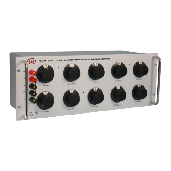
HARS-LX
Laboratory Standard Decade
Resistance Substituter
User and Service Manual
Copyright © 2014 IET Labs, Inc.
Visit www.ietlabs.com for manual revision updates
HARS-LX-im November 2014
IET LABS, INC.
www.ietlabs.com
Email: info@ietlabs.com
TEL: (516) 334-5959 • FAX: (516) 334-5988
Advertisement
Table of Contents

Related Manuals for IET Labs HARS-LX


Summary of Contents for IET Labs HARS-LX
- Page 1 ♦ PRECISION INSTRUMENTS FOR TEST AND MEASUREMENT HARS-LX Laboratory Standard Decade Resistance Substituter User and Service Manual Copyright © 2014 IET Labs, Inc. Visit www.ietlabs.com for manual revision updates HARS-LX-im November 2014 IET LABS, INC. www.ietlabs.com Email: info@ietlabs.com TEL: (516) 334-5959 • FAX: (516) 334-5988...
- Page 2 ♦ ♦ PRECISION INSTRUMENTS FOR TEST AND MEASUREMENT IET LABS, INC. www.ietlabs.com Email: info@ietlabs.com TEL: (516) 334-5959 • FAX: (516) 334-5988...
- Page 3 WARRANTY We warrant that this product is free from defects in material and workmanship and, when properly used, will perform in accordance with applicable IET specifi cations. If within one year after original shipment, it is found not to meet this standard, it will be repaired or, at the option of IET, replaced at no charge when returned to IET.
- Page 4 WARNING OBSERVE ALL SAFETY RULES WHEN WORKING WITH HIGH VOLTAGES OR LINE VOLTAGES. Dangerous voltages may be present inside this instrument. Do not open the case Refer servicing to qualifi ed personnel HIGH VOLTAGES MAY BE PRESENT AT THE TERMINALS OF THIS INSTRUMENT WHENEVER HAZARDOUS VOLTAGES (>...
-
Page 5: Table Of Contents
Contents Chapter 1 Introduction ................1 1.1 Introduction ......................1 Chapter 2 Specifications ................2 Specifications ........................ 2 Chapter 3 Installation ................4 3.1 Initial Inspection ....................4 3.2 Installation ......................4 3.3 Repackaging for Shipment ..................4 3.4 Storage ........................4 Chapter 4 Operation ..................5 4.1 Initial Inspection and Setup .................. - Page 6 Figures and Tables Figure 1-1: HARS-LX Resistance Substituter ..........1 Figure 2-1: Typical Operating Guide Affixed to Unit ........3 Figure 4-1: Kelvin Bridge Connections ............7 Table 5-1: Trimming Potentiometers ............11 Figure 5-1: Typical Trimmer Board ...............11 Table 5-2: Replaceable Parts List ..............12...
-
Page 7: Chapter 1 Introduction
HARS-LX Series Chapter 1 INTRODUCTION The HARS-LX is designed to allow very convenient 1.1 Introduction maintenance of calibration over time. Most decades are adjustable without changing components or sol- The HARS-LX Series Laboratory Standard Decade dering resistors. The decades for the 100 Ω through Resistance Substituter provides a very broad-range 1 MΩ... -
Page 8: Chapter 2 Specifications
HARS-LX Series Chapter 2 SPECIFICATIONS For convenience to the user, the pertinent specifications are given in a typical OPERATING GUIDE, like the one shown in Figure 2.1, affixed to the case of the instrument. SPECIFICATIONS Total Max current Max power Temperature... - Page 9 HARS-LX Series Mechanical Information: Model Dimensions Nominal Weight 7.7 cm W x 7.7 cm H x 8.4 cm D 0.45 kg 1 decade (3" W x 3" H x 3.3" D) (1.0 lb) 37.5 cm W x 8.9 cm H x 10.2 cm D 2.0 kg...
- Page 10 HARS-LX Series Specifications...
-
Page 11: Chapter 3 Installation
3.1 Initial Inspection 3.3 Repackaging for Shipment IET instruments receive a careful mechanical and If the instrument is to be returned to IET Labs, contact electrical inspection before shipment. Upon receipt, the Service Department at the number or address, verify that the contents are intact and as ordered. -
Page 12: Chapter 4 Operation
The highest quality low emf components are used in 2-terminal measurements may be made by shorting the HARS-LX series. In particular, the terminals are CURRENT HI to SENSE HI, and CURRENT LO made of gold plated tellurium copper, which exhibits to SENSE LO, preferably with shorting links or other low emf and low resistance. -
Page 13: Dial Setting
To maintain the maximum possible accuracy and pre- The resistance setting may be read directly from the cision, power applied to the HARS-LX should be kept dial settings. For additional flexibility and range, as low as possible, preferably below 0.1 W. For best each decade provides a “10”... -
Page 14: Meter Shunt Applications
HARS-LX Series 4.8 Meter Shunt Applications For maximum protection and accuracy, limit power input to HARS-LX to 1 Watt. This may be accom- plished by placing a resistor in series with the bridge To measure the current in a 4-terminal resistor: generator or battery. - Page 15 See Figure 4-1. Figure 4-1: Rheostat Dial In order to eliminate contact resistance and thermal emf, the HARS-LX integrates the rheostat as shown in Figure 4-2. This way, the wiper is in the low potential circuit, which is the high impedance lead.
-
Page 16: Chapter 5 Maintenance
5.2 Preventive Maintenance If the HARS-LX is employed as a stand alone device, the following should be observed: • Calibration Interval Keep the unit in a clean environment. This will help •... -
Page 17: General Considerations
HARS-LX unit, and/or the 5.3.4 Calibration Procedure uncertainty of the measurement instrumenta- tion has to be considered in the calibration To calibrate the HARS-LX unit, proceed as follows: Test Uncertainty Ratio (TUR). 1. Set up the calibration equipment in the re- •... -
Page 18: Adjustments
If one or more resistances fall outside the limits, the To trim or adjust any resistances, proceed as follows: associated resistor should be adjusted. There is a 1. Stabilize HARS-LX at laboratory tempera- trimming network provided for each resistance in ture of 23 °C for at least 8 hours. - Page 19 HARS-LX Series Potentiometer Designation Potentiometer Designation Switch Position All decades but 1 k Ω 1 kΩ decade T10 (1 M steps only) Table 5-1: Trimming Potentiometers Trim Potenti- ometers Figure 5-1: Typical Trimmer Board Maintenance...
-
Page 20: Replaceable Parts List
10 kΩ/step Decade Switch Assembly Not Shown HARS-4000-LX-100k 100 kΩ/step Decade Switch Assembly Not Shown HARS-4000-LX-1M 1 MΩ/step Decade Switch Assembly Not Shown HARS-4000-LX-10M 10 MΩ/step Decade Switch Assembly Table 5-2: Replaceable Parts List Figure 5-2: HARS-LX Replaceable Parts Maintenance...
Need help?
Do you have a question about the HARS-LX and is the answer not in the manual?
Questions and answers