
Summary of Contents for Merriott EMMETI ClimaAir CA VS 7-2P
- Page 1 Installation, operating & instruction manual ClimaAir Fan Convector PLEASE LEAVE THIS MANUAL WITH THE END USER...
-
Page 2: Table Of Contents
Contents Product Information Integrated and Remote Control Setup Menu Safety and General Information Setup Menu Safety Information 0-10V Models General Information 0-10V Fan Control Technical Data Connection Diagram with 0-10V DC Dimensions Thermostats/Signals Fan Speed Regulation Installation Positioning the Unit User Instructions Installation Clearances Integrated and Remote Control Operation... -
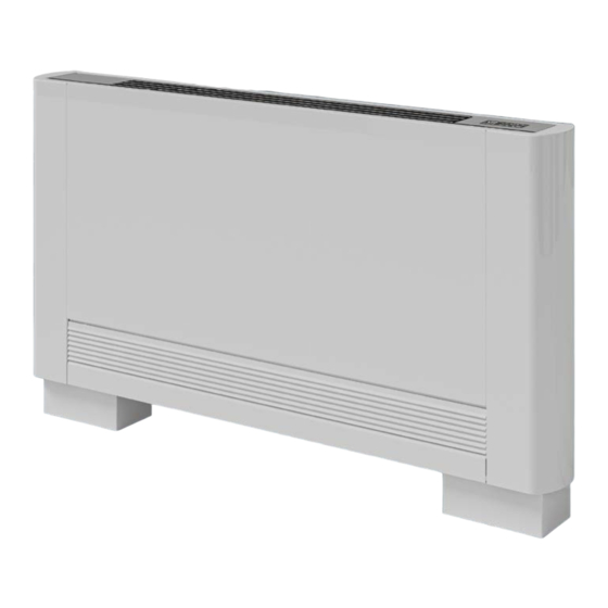
Page 3: Product Information
ClimaAir Product Information We want to thank you for choosing one of our products. We are confident that you will be happy with your selection because it represents the state of the art in the technology of climate control. ClimaAir Fan Convectors are available with casing or without casing, in 5 different lengths. CA VS - Surface Mounted Models can be mounted vertically on the wall or horizontally on the ceiling, with the option for integrated controls (not ceiling), remote control or 0-10V option with BMS input or 0-10V remote control input. -
Page 4: Safety And General Information
ClimaAir Safety and General Information 1.1 Safety Information may happen to be applied to the unit, prior to finalising installation. This appliance MUST NOT be installed in a bathroom or other This product must not be installed similar high humidity areas. immediately below a socket outlet. -
Page 5: General Information
ClimaAir 1.2 General Information Avoid prolonged physical contact with the direct air flow. Do not leave the room closed for long periods. Periodically open Before proceeding with the installation, unpack the product and the windows to ensure fresh air exchange. make sure that all the components are present, and that there is no concealed shipping damage. -
Page 6: Dimensions
ClimaAir Safety and General Information (cont...) 1.4 Dimensions CA VS - 2-Pipe Models FRONT VIEW SIDE VIEW G3/4"EK G3/4"EK 37.5 37.5 G3/4"EK G3/4"EK ∅ 14 ∅ 14 Note: Optional feet are 82mm Dimensions Model CA VS 7-2P CA VS 9-2P CA VS 11-2P CA VS 13-2P CA VS 15-2P... - Page 7 ClimaAir CA VS - 4-Pipe Models FRONT VIEW SIDE VIEW G3/4"EK G3/4"EK 37.5 37.5 G3/4"EK G3/4"EK ∅14 ∅14 Note: Optional feet are 82mm Dimensions Model CA VS 7-4P CA VS 9-4P CA VS 11-4P CA VS 13-4P CA VS 15-4P 1135 1335 1535...
-
Page 8: Installation
ClimaAir Installation 2.1 Positioning the Unit This unit must not be installed in a bathroom, in damp The following instructions refer to units with standard water areas or places with possible contact with water. connections on the left hand side. Avoid installing the unit: Make sure that: >... -
Page 9: Side Opening
ClimaAir 2.3 Side Opening A Cover > On the left-hand side, lift the cover that protects the screw, B Fixing screws loosen the screw that fixes the left panel, then move it slightly C Left panel to the left and lift it up. D Right panel >... -
Page 10: Horizontal Ceiling Installation (Vs, Vsi)
ClimaAir Installation (cont...) 2.5 Horizontal Ceiling Installation (VS, VSI) Using the paper template provided, trace on the ceiling the Fully tighten all 6 fixing screws. position of the two fixing brackets and the two rear screws. For installation of the CA VS versions, horizontal condensation Using a suitable drill, make the holes and insert the wall plugs collection tray accessory kits are available. -
Page 11: Air Intake Grille Fixing
ClimaAir 2.7 Air Intake Grille Fixing A Insert grille tab into lower bracket slot If the inlet grille is accidentally removed or left loose the fan will B Fixing screws stop and the grille safety alarm will activate. To prevent this from C Correct position of grille tab happening the grille can be secured using the 2 screws provided (type TC 4.2 x 9.5mm). -
Page 12: Condensate Discharge
ClimaAir Installation (cont...) 2.9 Condensate Discharge > The condensate discharge pipes must be suitably sized (minimum If the condensate needs to be discharged into a container, the inside pipe diameter 16mm) and the pipeline positioned so that container must be open to the atmosphere and the tube must it keeps a constant inclination, never less than 1%. -
Page 13: Filling And Venting The System
ClimaAir 2.10 Filling and Venting the System > When starting up the system, make sure that the return valve is When water starts coming out of the air vents, close them open. Refer to section 4.3 for correct setting. If there is no electric and continue filling the system until reaching the nominal power and the actuator valve has not already been powered up, system pressure. -
Page 14: Electrical Connections
ClimaAir Installation (cont...) 2.11 Electrical Connections > Electrical connection must be made by a qualified Switch off electrical supply before making electrical connections. electrician in accordance with local and national > Remove control box cover. wiring regulations. > Make electrical connections to pcb. The unit must be connected to the mains supply using >... - Page 15 ClimaAir Cleaning the Filter Never use the unit without filters. > The appliance is fitted with a safety switch that Remove any dust with a vacuum cleaner. prevents operation of the fan with the front grille > Wash the filter with clean running water. Do not use missing or out of position.
-
Page 16: Faults And Troubleshooting
ClimaAir Faults and Troubleshooting 3.1 Troubleshooting > In the event of a water leak or malfunction immediately The fan does not activate even if there is hot or cold water in cut off the power supply and close the system valves to the hydraulic circuit. -
Page 17: Instructions 2-Way Valve
ClimaAir Instructions 2-Way Valve 4.1 Warnings These instructions relate to the valve kits supplied with For correct operating performance of this unit, the flow the unit. The general instructions and basic safety rules and return pipework must be correctly fitted according to detailed in this manual should be followed. - Page 18 ClimaAir Instructions 2-Way Valve (cont...) Pipe Connection from Wall - with Optional 90° Elbow Fitting A Thermostatic head B 2-way valve C 90° elbow fitting (optional – can be supplied as accessory) D Return valve connection PLEASE NOTE: Valves are factory fitted but not tightened. For through-the-wall connections 90°elbow C (or similar) should be used.
- Page 19 ClimaAir Pressure Drop Diagram Pressure drop figures based on the 2-way valve fully open position.
-
Page 20: Return Valve Pre-Setting Screw Adjustment
ClimaAir Instructions 2-Way Valve (cont...) 4.3 Return Valve Pre-Setting Screw Adjustment > The system can be balanced using the return valve(s) fitted to Mark a reference point “x” aligned to the pin slot for adjustment the unit. The following procedure must be carried out for correct of the pin (B) . - Page 21 ClimaAir Pressure Drop Diagram Pressure drop figures based on the return valve setting. 0.01 0.001 10.0 100.0 1000.0 Q [kg/h] Return Valve Settings Pos. 1,25 1,75 2,25 2,75 5,5 Turns Pos. 0,09 0,38 0,58 0,69 1,07 1,37 1,72 2,13 2,75 3,06 3,23 3,31...
-
Page 22: Valve Insulation
ClimaAir Instructions 2-Way Valve (cont...) 4.4 Valve Insulation Water pipes and joints must be thermally insulated. Avoid partial insulation of the pipework. Check that the insulation is sufficiently tight to avoid condensation and dripping, but not too tight in case of damage to pipework. -
Page 23: Control Panel Connection And Configuration
ClimaAir 23 Control Panel Connection and configuration 5.1 Connection and Configuration of Control Panel The control panel on each unit has the following A 10kΩ water temperature probe attached to the heat exchanger connection options: controls fan operation. In heating the fan will operate when the water temperature reaches 30°C, and in cooling the fan will >... -
Page 24: 2-Pipe & 4-Pipe Models With Integrated Control
ClimaAir Control Panel Connection and Configuration (cont...) 5.4 2-Pipe & 4-Pipe Models with Integrated Control Water temperature probe (10kΩ) Boiler switched output (voltage free contact max 1A) Water temperature probe (10kΩ) 4-pipe only Chiller switched output (voltage free contact max 1A) Presence detector input (if closed, the fan coil unit is Air temperature probe (10kΩ) placed in standby) -
Page 25: 2-Pipe & 4-Pipe Models With Wall-Mounted Remote Control
ClimaAir 25 5.5 2-Pipe & 4-Pipe Models with Wall-Mounted Remote Control boiler switch output (voltage free contact max 1A) Serial connection for wall-mounted remote control +AB- (respect AB polarity) chiller switch output (voltage free contact max 1A) Hot water temperature probe (10kΩ) Air probe optional (**) Cold water temperature probe (10kΩ) air temperature probe (10kΩ) -
Page 26: Connection Of Multiple Units Using Wall-Mounted Remote Control
ClimaAir Control Panel Connection and Configuration (cont...) 5.6 Connection of Multiple Units Using Wall-Mounted Remote Control > All functions of the fan coil can be controlled from a wall-mounted The RS485 should be a shielded two-core cable with a minimum remote control, and up to a maximum of 30 units can be controlled thickness of 0.35mm². -
Page 27: Remote Control Panel Mounting
ClimaAir 27 Error Messages Display Error Communication error. The circuit board expects continuous information exchange on the serial line with the wall-mounted control. If this exchange is lost for more than 5 minutes, an error warning is displayed, and the 6 flashes + pause unit deactivated. -
Page 28: Wiring Connection To Remote Control
ClimaAir Control Panel Connection and Configuration (cont...) 5.9 Wiring Connection to Remote Control Wiring connection to the remote control is made by inserting wires into the spring-loaded terminals on the back of the control. RS485 cable should be used to connect to terminals A and B, and 0.2 to 1.0mm rigid or flexible wires into the + - power terminals. -
Page 29: Integrated And Remote Control Setup Menu
ClimaAir 29 Integrated and Remote Control Setup Menu 6.1 Setup Menu The Setup Menu can be accessed through the control with the display switched off. Operation Display > Press the key "ON" for 10 sec. > The device turns on and the temperature appears >... - Page 30 ClimaAir Integrated and Remote Control Setup Menu (cont...) Adjust the Brightness of the Display To adjust the brightness: Display Operation > The brightness adjustment range is from 00 to 01 > Increase and decrease the brightness with the icons The brightness changes after confirming the modification. You can also reduce the brightness of the display through the control’s key.
-
Page 31: 0-10V Models
ClimaAir 0-10V Models 7.1 0-10V Fan Control For units with 0-10V fan speed modulation, motor regulation can Valve actuators should be activated from the external control. be made using an analogue 0-10V DC input with 25kΩ impedance. If the remote 0-10V thermostat kit is used, a water temperature sensor is available as an accessory. -
Page 32: User Instructions
ClimaAir User Instructions 8.1 Integrated and Remote Control Operation These controls provide room temperature regulation in AUTO, Anti-freeze protection is provided even in standby mode. SILENT, NIGHT and MAX programmes by using a temperature After 20 seconds from the last action, the panel brightness probe mounted in the lower part of the unit (integrated controls) will be reduced, and the room temperature will appear on or in the remote control. -
Page 33: Activation
ClimaAir 33 8.4 Activation Switch on the electrical power supply at the switched fused spur. To activate the device: Operation Display Press the "ON" stand-by key from off to on Select one of the 4 operating modes by pressing the relative key. 8.5 Heating/Cooling Mode Settings Operation Display... -
Page 34: Automatic Operation
ClimaAir User Instructions (cont...) 8.8 Automatic Operation Operation Display Press and hold the AUTO key. The function being activated is indicated by the relevant symbol appearing on the display. Fan speed adjustment is carried out automatically between the minimum and maximum values, according to the difference between room temperature and set temperature. -
Page 35: Room Temperature Probe Regulation Offset
ClimaAir 35 8.14 Room Temperature Probe Regulation Offset As the detection probe is towards the bottom of the device, the Use this adjustment with care, and only after having confirmed a temperature detected may at times differ from the actual room discrepancy compared with the actual room temperature using a temperature. - Page 36 Merriott UK & Ireland Purmo Group (UK) Ltd, Eastern Avenue, Team Valley, Gateshead, Tyne & Wear NE11 0PG Tel: 0330 0415 472 sales@merriott uk.com sales@merriott .ie www.merriott uk.com / www.merriott .ie Follow us on @Merriott UK and...
Need help?
Do you have a question about the EMMETI ClimaAir CA VS 7-2P and is the answer not in the manual?
Questions and answers