Table of Contents
Advertisement
Quick Links
Advertisement
Table of Contents

Related Manuals for Palmer MicroCALL+


Summary of Contents for Palmer MicroCALL+
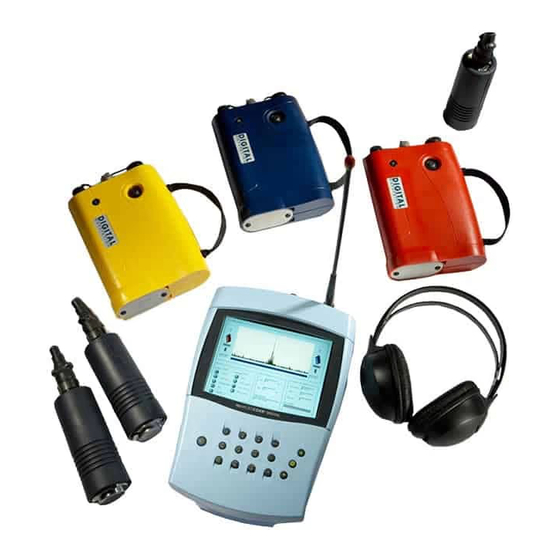
- Page 1 MicroCALL+ User Manual Palmer Environmental Ltd Ty Coch House Llantarnam Park Way Cwmbran NP44 3AW MicroCALL+ User Manual United Kingdom MAN-066-0001 Issue A Tel: +44 (0) 1633 489479 Fax: +44 (0) 1633 877857 Date 01/02/08 Email: info@palmer.co.uk Written by JP...
-
Page 2: Table Of Contents
Contents Contents Page 2 Introduction Page 3 Principle Of Correlation Page 4 Battery Installation And Charging Page 5 Switching On The Basestation Page 6 Outstation Deployment Page 7 Operating The Basestation Page 8 Correlate Page 9 Correlation Mode Page 10 Correlation Setup Page 11 Calculate Velocity... -
Page 3: Introduction
The system builds on the proven reputation of MicroCorr Correlators and includes ad- vanced features only previously available in Palmer’s DigiCALL PC based unit to maxi- mise performance, ease of use and rugged compact packaging for daily deployment. -
Page 4: Principle Of Correlation
Principle of Correlation In the "classic" correlation process, two sensors are deployed on pipe fittings ("dry" connection) or connected to hydrants ("wet" connection). The sensors are positioned either side of the suspected leak position. Noise is created by the leak as it escapes from the pipe under pressure. This noise is conducted in both directions away from the leak through the pipe wall (as minute vibrations) and through the water column (as a pressure wave). -
Page 5: Battery Installation And Charging
Any misuse may result in explosion or fire. They must not be used in any other application or used with any other equipment. Only batteries/battery-packs supplied by Palmer Environmental must be used. The sealed battery packs contain circuitry to prevent overcharging and over- discharging. -
Page 6: Switching On The Basestation
Switching on the Basestation Switch the Basestation on by pressing the On/Off key momentarily. A number of sys- tem tests and calibrations are carried out on power up to ensure the unit is fully func- tional. After a few seconds the main screen will appear on the display as shown below: From the main screen select the required menu/function by pressing the assigned key. -
Page 7: Outstation Deployment
Outstation Deployment Once the batteries have been installed and charged in the Basestation and the Outsta- tions, connect the antennas, sensor cables and sensors to each Outstation. Switch on each Outstation by pressing the On/Off button. The LED will flash Orange then Green (or Yellow/Red depending on battery status) to indicate the unit is ready for use. -
Page 8: Operating The Basestation
Operating the Basestation The Basestation has an alpha-numeric keypad, similar to that of a mobile phone. Keys include a full stop, cancel, enter and up/down arrows. Navigation through the menus uses combinations of these keys. Most functions can be selected by the number dis- played on screen. -
Page 9: Correlate
Correlate Selecting Correlate (key 1) from the main screen opens the correlation screen. With the Outstations deployed and turned on, press the Enter key to start the correlation. Correlation can be stopped at any time by pressing the Enter key a second time. Press Enter key for Correlation Set-up Press Enter again to start Correlation Press Enter a third time to stop Correlation. - Page 10 Correlation Setup The Stations to be used for Correlation are selectable. Flexibility, Efficiency, Simplicity...
-
Page 11: Correlation Mode
Correlation Mode Either 2 station or 3 station. 2 Station is standard mode at power-up when using it the Correlator estimates the velocity of sounds in the pipe work from user selected pipe material and diameter. This mode is also used in stations that contain more than one pipe material, results from this mode can be combined in a linear regression calculation to improve on the accuracy of the velocity calculation. -
Page 12: Calculate Velocity
Calculate Velocity A velocity check gives a more accurate velocity of the pipe to be correlated instead of using the default velocity value. In some circumstances the default velocity may be slightly off due to adverse conditions, therefore it may be required that a manual veloc- ity check be performed to ensure a correct correlation. -
Page 13: Peak Suppression Screen
Peak Suppression Screen Press 6(Peak Suppression) To suppress a section of the time delay range from the current correlation. This may be used to remove known leaks or demand usage that may be hiding unknown leaks. Move the dashed cursor line to the start point of the data to be removed and press 1 to select a start point. -
Page 14: Regression Analysis
Regression Analysis Regression Analysis provides an additional way of pinpointing leak positions by using a set of correlation results, rather than an individual correlation result. This also pro- vides a way of measuring an accurate velocity. Where the same pipe material and diameter are used within the network, the time de- lay / distance relationship of the correlation is theoretically linear. - Page 15 After at least two correlation results have been saved, from the main screen, press 4 (Regression Analysis). Press 1 to add the first result. At this point the file screen will appear. Select one of the saved correlations. The control unit will then ask for the “Static Outstation” colour. (This is the outstation that was not moved during the correlations.) The control unit will store the material and diameter of the first correlation result and compare with the next result(s) to be added, this ensures these details remain constant.
- Page 16 Press 1 to add the second correlation result. A second cross will appear and a line will pass through both. The distance from the static sensor to the leak and the calculated velocity will be shown. We highly recommend the user add a third result for a more con- fident result.
-
Page 17: Settings
Settings Options 1,2 and 3 allow the setting of length units both Metric and Imperial and the time units selectable are seconds or milliseconds, radio power can be low or high. High—gives greater range but shortens battery life. Option 4, this allows access to the pipe material database where you can define your own materials also velocities for specific diameters. -
Page 18: Listening Mode
Settings Listening Mode When listening to an Outsatation the transmission will occur in fifteen second blocks. This is due to the system using a single radio frequency, it then allows listening mode to finish according to the user’s wishes. See below for screenshot. -
Page 19: Pipe Parameters
Settings Pipe Parameters This enables a user to define a pipe containing up to 10 segments. This screen allows a pipe containing up to ten segments to be defined. To add a new pipe segment, click the “Add” button and the “Enter Pipe Segment” box will be displayed. -
Page 20: Pipe Materials Database
Settings Pipe Materials Database Enables the user to manually define up to 20 pipe materials for use on the current cor- relation. -
Page 21: Information
Information Select the required menu/function by pressing the assigned key. Press key 1 to enter editing of specific information of the current Correlation. Press key 2 to show system status— battery power, radio signal and sensor to unit connection. Press key 3 to display current version of Firmware and software. Press key 4 to enter the Factory service diagnostics. -
Page 22: Filters
Filters If correlating with pipe data entered, the default filter settings will be used depending on the properties of the pipe. Some times this may not be accurate enough to filter out unwanted frequencies, so the user may wish to alter the filer settings to remove certain frequencies that are influencing the current correlation. - Page 23 Press 1 (Select cursor) This toggles between the two cursor lines. Only the longer dashed cursor line can be moved. Press 2 (Low cut-off) When the left cursor line has be selected the low cut off op- tion is displayed. Move the left cursor to the required position and press 2. This will remove all frequencies to the left of the cursor line.
-
Page 24: Technical Specification
Mixed material 10 sections Battery level indication For all system units Battery type Rechargeable Lithium ion batteries, field replaceable Firmware User upgradeable from www.palmer.co.uk Dimensions 261mm x 185 x 88mm Weight Operating temperature -15°C to +50°C Enclosure Plastic moulded case Connectors... - Page 25 Technical Specification Outstation Radio communication Single frequency digital transceiver Radio frequency UHF (local regulations apply) Controls ON/OFF with LED status light Connections Headphones External antenna Sensor Battery type Rechargeable Lithium ion batteries, field re- placeable Battery life >18 hours Antenna External antenna Dimensions 203mm x 136 x 51mm...
-
Page 26: Contact
Tel: +44 (0) 1633 489479 Fax: +44 (0) 1633 877857 General Enquires: information@palmer.co.uk Technical support: support@palmer.co.uk Web: http://www.palmer.co.uk Note Palmer Environmental reserves the right to change products, services or specifications without notice. MicroCALL+ User Manual MAN-066-0001 Issue A Date 01/02/08 Written by JP...
Need help?
Do you have a question about the MicroCALL+ and is the answer not in the manual?
Questions and answers