Table of Contents
Advertisement
Quick Links
Advertisement
Table of Contents

Subscribe to Our Youtube Channel
Related Manuals for BAYKON BX 6

Summary of Contents for BAYKON BX 6
- Page 1 BAYKON B X 6 WEIGHING TERMINAL OPERATION MANUAL 03/2008...
-
Page 2: Table Of Contents
App 7 BX 6 Model Identification PRECAUTIONS DO NOT LET THE UNAUTHORIZED PEOPLE INTERFERE THE INDICATOR. FOR SAFETY OPERATION BX 6 SHOULD BE SUPPLIED WITH GROUNDED VOLTAGE NETWORK. CHECK THE POWER VOLTAGE AND GROUND CONNECTIONS BEFORE ENERGISING BX 6. DON’T ENERGISE BX 6 BEFORE MAKING LOAD CELL CONNECTION. -
Page 3: Features
1. Features BX 6 is a high tech weighing terminal designed for various industrial weighing applications. It’s available to load custom based application software to BX 6 besides standard application software. Standard application software is for labeling and for truck scale applications. -
Page 4: Installation And Commissioning
BX 6 operates with 230 VAC 50 Hz and supplied with power cable. There are two jumpers on BX 6’s weighing board for calibration and for On/Off switch. To change the position of these jumpers, open the housing and perform needed changes and/or control them before energizing the indicator. - Page 5 The input resistance of the load cells that you will connect should be more than 58 . The sense pins of BX 6 should be connected. The sense and excitation pins with the same polarity should be short circuited at the connector side in 4 line load cell wiring.
-
Page 6: Front Panel And Key Functions
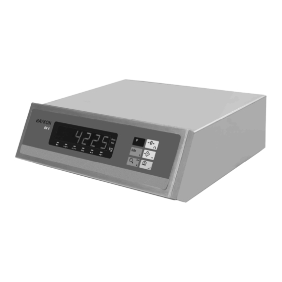
Figure 2. Front panel view of BX 6 3.1 Display The weight display of BX 6 is seven segment LED. Under the weight display 6 LEDs take place related to weighing. At the right side of the display there are three LED’s for indicating the net, gross and the unit. -
Page 7: Key Pad
3.3 Key Lock BX 6 has ability to lock the keys to avoid unauthorized person’s interfere. You can activate or deactivate this function by pressing “ F “ and “Key Lock” keys sequentially. The LED with key sign which takes place at the bottom of the info LEDs at... -
Page 8: Serial Interface
4. Serial Interface There are two type of serial output in BX 6. The first is from PC board ( COM1 ) and the data output of this interface is depend on the application software located on the PC board. The second type optional data output is from weighing board and is for interfacing with the weighing board directly. -
Page 9: Alibi Memory
6. Alibi Memory The alibi memory of BX 6 shall be installed and activated for legal metrologic usage, because of the free programmable application software ability of BX 6. The alibi records can be displayed or printed. To reach a definite record you have to enter to parameter 802. After reaching the desired record, the recorded data can be view from display. -
Page 10: Programming And Calibration
7. Programming and Calibration In this section you will find the programming and calibration procedure of indicator according to your application. The signs those take place on the lower right corner of the keys indicate the function of the keys in programming menu. The basic meanings of these keys are given in the table below. - Page 11 0_ _ 01 _ PARITY INTERFACE INT 1 D.FORMAT BAUD HANDSHAKE 02 _ PARITY INT 2 D.FORMAT BAUD HANDSHAKE S. MODE 04 _ MIN. PRT PRT CTRL PRINTER 1_ _ 11 _ CONFIG START UP BUZZER 12 _ FĐLTER F.ADJ NO FILTER FASTEST SLOWEST...
- Page 12 7.3 Programming [0--] Interface Block You can reach the parameters about optional serial interface of BX 6 indicator in this section. [01-] Interface-1 This sub-block includes the parameters about the 1 optional serial interface of BX 6. [010 X ] Data Format 0 : No data transfer.
- Page 13 [021 X] Baud Rate 0 : 1200 Baud 1 : 2400 Baud 2 : 4800 Baud 3 : 9600 Baud 4 : 19200 Baud 5 : 38400 Baud 6 : 57600 Baud [022 X] Handshake 0 : No Handshake 1 : Xon/Xoff [023 XX] Address You can define a device address between 1 and 99 by this parameter.
- Page 14 [1--] Configuration Block In this block the parameters take place which are being used to set BX 6 according to your application. [11-] Start Up [114 X] Buzzer 0 : No Buzzer. 1 :The Buzzer will active when a key pressed, in case of error messages or when the alarm is active.
- Page 15 [204 X] Auto Zero Tracking AZT automatically readjusts the scale to zero for compensating selected small deviation per second around center of zero. 0 = disable 1 = ± 0,5e 2 = ± 1e 3 = ± 3e [205 X] Tare 0 = Tare disabled 1 = Pushbutton Tare [206 X] Motion Detector...
- Page 16 [212 ] Range 2 Press Tare key to enter this parameter. [CAP2 ] [ XXXXXX ] The capacity of the first weighing range ( Select from Appendix 6 ) will be entered here via Tare and Zero keys and confirmed with Enter key. [ XXXXXX ] Display resolution of the second weighing range will be selected by Zero key and confirmed with Enter key .
- Page 17 [31-] Adjustment In this sub-block you can only perform zero adjustment or span adjustment without full calibration operation. [310 ] Zero Adjustment This parameter is only being used for refreshing the zero level of the scale to prevent wrong weighing from zero drifts. Begin the zero adjustment by pressing Enter key.
- Page 18 Alibi board and records by pressing Print key. [9--] Diagnostics The operations about checking and testing BX 6 can be made here. [90-] Tests [900 ] Key Pad Press Enter key. [900 --] message appears on the display. In this step every keys ASCII code will be shown on the display as you press the related key.
- Page 19 The parameters take places in this section are the calibration parameters of BX 6. These values can be used when a problem occurs about the calibration of BX 6 if they had been noted before. You can refresh the calibration by entering correct values.
-
Page 20: Options
8. Options 8.1 Serial Interface 2 additional serial interfaces ( for weighing board interfacing ) can be added to BX 6 in addition to standard COM1. One of the outputs of optional serial interface card is RS232, and the other one can be selected as RS232, RS485 or 20 mA ASCII CL. 012 parameter should not be selected as 2 ( hardware handshake ), for programming the second optional data output as RS232C. -
Page 21: Ethernet
8.2 Ethernet If the connection given in the table below is made with Ethernet option, BX 6 will be able communicate with the peripherals. The Ethernet output can be done from PC board for data transfer. Pin configuration of RJ45 Ethernet connector is indicated below:... -
Page 22: Housing
9. Housing BX 6 side view OPTION COM1 KEYBOARD □ □ □ □ □ □ □ I/O3.3 I/O4.8 POWER ON/OFF 230 VAC, 50Hz 150mA ETHERNET PARALLEL PORT MONITOR LOAD CELL BX 6 rear view... -
Page 23: App
Appendix 1: Status Bytes in Continuous Data Output Definition Table for Status A Bits 0, 1 and 2 Bits 3 and 4 Decimal Increment size point XXXXOO XXXXXO XXXXXX XXXXX.X XXXX.XX XXX.XXX XX.XXXX X.XXXXX Definition Table for Status B Bit 0 Gross=0 Net=1 Bit 1... -
Page 24: App
Appendix 2: Host Mode Data Structure If related parameters are adjusted for host communication, BX 6 weighing board will be connected to your system in Host Mode. BX 6 weighing board supports “0x03” and “0x10” functions. 03 (0x03) Reading Holding Registers This function code is being used to read the information in the register addresses which have been permitted to be read in holding registers. - Page 25 Exception codes : 1 : Function code is not supported. 2 : Out of beginning and ending address range. 3 : Invalid value entrance 4 : Operation error. 16 (0x10) Preset Multiple Registers This function code is being used to change the information in the register addresses which have been permitted to be written in holding registers.
- Page 26 Exception codes 1 : Function code is not supported. 2 : Out of beginning and ending address range. 3 : Invalid value entrance or wrong byte number. 4 : Operation error. Error Check Calculating : CSUM = 0 – (Slave_Add + Function + … + Last_data) (STX and CSUM are neglected while calculating CSUM) Address R/W Word...
-
Page 27: App
If parameters are adjusted for Modbus option; the BX 6 indicator will be connected to MODBUS RTU system as slave. BX 6 indicator is defined in the system by the address info entered in the address parameter ( for RS 485 ) and supports “0x03” and “0x10” functions. -
Page 28: App
Appendix 4: Trouble Shooting BX 6 weighing terminal had been designed as a very reliable and virtually error free instrument. However if there is an error occurs, do not attempt to repair the equipment before understanding what caused the error. Note the problems you have with your instrument and the error messages shown on the display. -
Page 29: App
Appendix 5: Parameter’s Default Table Interface Block Calibration Block 01- Interface 1 30- Calibration 010 Data Format 0 = Not used 300 Gravity 011 Baud rate 3 = 9600 301 Calibration 31- Adjustment 012 Hand shake 0 = No 013 Address 310 Zero adjustment 014 Data length and Parity 0 = 8 bit, no parity... -
Page 30: App
Appendix 6: Calibration Table The n= Max capacity / e values are given in the table below. Use this table while selecting your Max and e values. -
Page 31: App
Appendix 7: Model Identification BX 6 Below, you will find the order coding system to identify the features of your BX 6 indicator. BX 6. C D E. F G H Alibi Memory Blank = Not used =74000 records =149000 records... - Page 32 Notes :...
- Page 33 Notes :...
- Page 34 BAYKON A.Ş. Kimya Sanayicileri Organize Sanayi Bölgesi Organik Cad. No:31 Tepeören, 34956 Đstanbul, TURKEY Tel : 0216 593 26 30 (pbx) Fax : 0216 593 26 38 e-mail: baykonservis@baykon.com http:// www.baykon.com...
Need help?
Do you have a question about the BX 6 and is the answer not in the manual?
Questions and answers