
Related Manuals for HWM Wi5

Summary of Contents for HWM Wi5
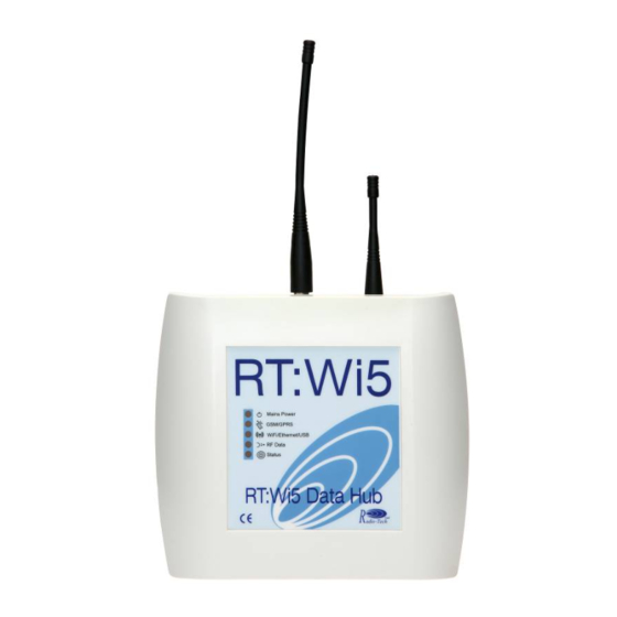
- Page 1 Wi5 Data Concentrator User Manual Version 14 Warning: This manual contains important safety and operating information. Please read, understand and follow the instructions in the manual.
-
Page 2: Table Of Contents
TABLE OF CONTENTS DESCRIPTION Technical Specifications Radio Receiver Data Recording Data Transfer Monitoring Unit Status Unit Configuration COMMISSIONING Step 1: Inspecting Package Content Step 2: SIM Card installation (GPRS Version) Step 3: Connecting the product Step 4: Interpreting Front Panel LEDs Step 5: Confirming Data Transfer CONFIGURING Configuration using USB port... - Page 3 Response Codes Table of commands 6.3.1 HELP 6.3.2 STATUS 6.3.3 SET DATETIME 6.3.4 SET TZONE 6.3.5 SET FTP 6.3.6 SET GPRS 6.3.7 SET NTP 6.3.8 FORCE SYNC 6.3.9 CONFIG 6.3.10 SET NEXT FTP TIME 6.3.11 SET SUMMARY TIME 6.3.12 SET FTP RETRIES 6.3.13 DUMP REPORTS 6.3.14...
-
Page 4: Description
1 Description 1.1 Technical Specifications Power supply 12V – 2A DC input provided by external PSU (supplied) PSU compatible with AC Input: 90-264 VAC 50-60 Hz Battery Backup – supply power to the unit for 24 hours in the event of mains power loss (GPRS version only) ... -
Page 5: Radio Receiver
In the event that the Wi5 concentrator is offline for an extended period it will send stored data starting from the oldest record. The FTP server or email settings can be set to send the data to HWM Data Server or to another server. -
Page 6: Monitoring Unit Status
Filters can be used to reduce the amount of data sent to the server (ftp or email): Only allow particular transmitter IDs’ or packet types Reject particular transmitters IDs’ or packet types Reject a packet from a transmitter if it has already transmitted within ... -
Page 7: Unit Configuration
1.6 Unit Configuration The unit operation can be configured via local USB connection, or for GPRS versions via SMS. Please Refer to Product configuration paragraph for the procedure to change the concentrator‘s configuration. -
Page 8: Commissioning
Ensure one step is covered before going to the next. 2.1 Step 1: Inspecting Package Content RT-Wi5 Data Concentrator Mains Power Supply Unit – 12V DC output Configuration Cable (USB A/B) – optional Antennas (GSM SMA / UHF BNC – VHF is... -
Page 9: Step 2: Sim Card Installation (Gprs Version)
2.2 Step 2: SIM Card installation (GPRS Version) If not already equipped by HWM the SIM card can be installed using the following procedure: Remove the front cover Install the SIM card into the SIM card connector as shown below: ... - Page 10 Only use the battery supplied with the unit. Failure to do so could result in product damage. Connect the Ethernet cable (if applicable) Reinstall the top cover Connect the external GSM and Radio antennas to the connectors as ...
-
Page 11: Step 4: Interpreting Front Panel Leds
If using a heavy RF cable for GSM or Radio connection use a strain relied on the cable to avoid stressing the connector, with excessive stress there is risk of cracking the case Connect the external Power Supply Unit DC connector into the location ... -
Page 12: Step 5: Confirming Data Transfer
o Data Transfer (In/Out) : LED Flashes RF Data– VHF or UHF version dependent (ORANGE LED): o Data Coming In : LED flashes Status (RED LED): o No Fault: OFF o SIM card not recognized / no registration on the GSM network / poor GSM signal (less than 2 bars): single flash every 2 seconds o SD Card not recognized: double flash every 2 seconds o Time Synchronization failed : three flash every 2 seconds... - Page 13 To test the connection to the server: • enter “dump reports” (without the quotes). If there are any active transmitters within range the Wi5 should display the packets ready to be sent. • enter “upload reports” (without the quotes). The Wi5 should contact the specified server, send the data then confirm if the data transfer was successful.
-
Page 14: Configuring
3 Configuring 3.1 Configuration using USB port 3.1.1 USB Driver It is recommended to download and install the latest Windows Driver D2XX from FTDI website: http://www.ftdichip.com/Drivers/D2XX.htm before proceeding. 3.1.2 Connecting the USB cable A standard USB A/B connector is required. Ensure the unit has the ... -
Page 15: Finding The Com Port In Windows
3.1.3 Finding the COM Port in Windows Click on Start Windows Menu Click on Settings Click on Control Panel Double Click on System Click on Hardware Tab Click on Device Manager Find the COM port number (in the following example COM8) 3.1.4 RS232 Communication Terminal Settings Any standard RS232 Terminal program can be used with the concentrator (HyperTerminal, Putty,…), ensure the following settings are used :... - Page 16 Once connection is established, enter the STATUS command, unit should respond with configuration summary. Example for GPRS version: STATUS 11/07/12 15:04:41 Version 7.3 GSM Version 07.03.000 GSM Signal 28 Comms mode GSM Logger ID ZZ99 Configuration disabled Power status: Mains SIM IP: 10.79.123.456 NTP server pool.ntp.org NTP protcol SNTP...
-
Page 17: Configuration Using Sms (Gprs Version Only)
3.2 Configuration using SMS (GPRS version only) This functionality is only available on GPRS concentrators from firmware revision 6.2 onwards. If you have an older firmware revision, please consult Radio-tech for advice on firmware upgrade. 3.2.1 Protocol This mode is used to remotely configure the GPRS concentrator via SMS. The protocol works as follows: STEP 1: User sends a SMS containing configuration commands... -
Page 18: Configuration Sms Format
3.2.2 Configuration SMS format The configuration SMS should follow the following format: COMMAND1 COMMAND2 … Phone Number where: • COMMAND1 ; COMMAND2; … are valid commands. Refer to configuration commands paragraph for exact command syntax Phone Number is an option. If present, the acknowledgment will be sent to this number instead. - Page 19 Acknowledgment SMS SET GPRS APN wyless.uk USER FAIL If an unknown command is contained in the configuration SMS it will not be acknowledged at all. This is to avoid sending unnecessary SMS when receiving SPAM...
-
Page 20: Configure The Unit To Assist During Radio Transmitters Installation Via Sms (Gprs Version Only)
3.3 Configure the unit to assist during radio transmitters installation via SMS (GPRS version only) This mode can be used when installing transmitters on site to verify that radio packets are received successfully. STEP 1 : Send install SMS to the concentrator phone number STEP 2 : concentrator sends acknowledgement SMS back “OK”... - Page 21 Mode of operation between steps 2 and 3 depends on the install SMS sent: “INSTALL ALL A” : concentrator sends SMS containing radio packet in ASCII when received “INSTALL ALL B” : concentrator sends SMS containing arrival time of ...
-
Page 22: Configuring Ethernet Model
3.4 Configuring Ethernet Model The Wi5’s IP address is set by default to obtain its IP address via DHCP server as configured by the factory. To enter details for a fixed IP address refer to section 6.3.23 on page 44 for the appropriate commands. -
Page 23: Installation
4 Installation The concentrator is not waterproof and as a result suitable for indoor use only. If outdoor installation is required, optional IP66 enclosure must be used. Once the two side lids are removed, simply take off the front cover. The disassemble unit and wall mounting punch through holes are shown below: Punch through... - Page 24 Alternatively industrial Velcro can be used at the back (red boxes on the picture). Also ensure that Mains Power is securely mounted to avoid falling out. For connections and tests, please refer to commissioning paragraph Steps 3 to 5...
-
Page 25: Troubleshooting Guide
5 Troubleshooting Guide Mains Power LED is single flashing Ensure that the PSU is plugged in the mains socket and the DC connector fully inserted in the GPRS concentrator Ensure that the PSU supplies 12VDC No USB Connection Ensure the computer has the latest FTDI driver installed (see driver ... -
Page 26: Configuration Commands Description
6 Configuration Commands Description 6.1 Syntax <CR> stands for Carriage Return In the examples, the characters in bold are the characters entered by the user Commands are not case sensitive 6.2 Response Codes A “000” reply means the command was recognised A “001”... - Page 27 Command Function GPRS Page Sets Password for Secondary ● SET FTP PASS2 FTP Server access Sets Destination Path within the ● SET FTP PATH2 secondary FTP Server Performs a configuration script ● SET FTP CONFIG upload from a specific FTP server Set FTP Mode Passive or ●...
- Page 28 Command Function GPRS Page Uploads data held in memory (and not previously uploaded) to ● ● UPLOAD REPORTS the programmes FTP/SMTP server. Displays Concentrator Firmware ● ● GET VERSION Revision Sets the phone number to ● SET AC FAIL NUMBER contact if mains failure ●...
-
Page 29: Help
Command Function GPRS Page ● Sets subnet mask SET SUBNET MASK ● Sets DNS address SET DNS ADDRESS 6.3.1 HELP HELP <CR> List all the commands available through the command line Example HELP SET FTP ADDRESS x – set the primary FTP address SET FTP USER x –... -
Page 30: Set Datetime
Note! This feature is only to be used when the time server is not available. When running from its internal clock the time on the Wi5 will drift so it is not recommended that the Wi5 is run in this mode for extended periods. -
Page 31: Set Ftp
6.3.5 SET FTP SET FTP ADDRESS x <CR> Sets the primary FTP server address, the address x can be set as an IP or URL. The address x cannot be longer than 31 characters SET FTP USER x <CR> Sets the username for primary FTP connection The username x cannot be longer than 15 characters... - Page 32 SET FTP PATH2 x <CR> Sets the path from the root (/folder/) of the secondary FTP server where the files will be transferred. By default the files will go in the root. If x is omitted, path will be set back to root. SET FTP CONFIG Performs a configuration script upload from user:pass@address/path...
-
Page 33: Set Gprs
6.3.6 SET GPRS SET GPRS APN x <CR> Sets the Access Point Name for GPRS connection. For firmware versions up to V7.9 the APN is limited to a maximum of 31 characters. From V7.10 onwards it can be up to 63 characters. -
Page 34: Set Ntp
Note 1: The DAYTIME protocol is available from firmware V6.8 onwards. The time is updated once per day. For Ethernet variants using the HWM “Cliff” email server, the time will also be updated whenever a connection to the server is made. -
Page 35: Config
6.3.10 SET NEXT FTP TIME SET NEXT FTP TIME x<CR> Sets the interval in seconds between each transfer of data from the Wi5 to the ftp or email server x is expressed in seconds – default 3600 sec Example... -
Page 36: Set Summary Time 600
– default is once a Example SET SUMMARY TIME 600 6.3.12 SET FTP RETRIES Advise HWM before changing this parameter SET FTP RETRIES x<CR> Sets the number of time will attempt to connect to the FTP server before aborting... -
Page 37: Dump Reports
6.3.13 DUMP REPORTS DUMP REPORTS<CR> Displays the radio packets in memory which will be transferred on the next FTP session Example DUMP REPORTS 200905081005488100E2AC480003C060DA4F 2009050810054882011BE209002B8000F08D 200905081005498A016F1E46815D00002D5E 2009050810054982016FAE03002C0197C2B8 2009050810054982016FAE03002C0197C2B8 200905081005508A016E960600CD010E8A9C 200905081005508200C67A43002801982860 200905081005508200442407002B8FFFA353 200905081005508A016F1446815D00002DF4 200905081005508201250C09002B80003800 20090508100551820151E20900298000BA89 2009050810055182016FAA03002C019C82FB … 6.3.14 UPLOAD REPORTS UPLOAD REPORTS<CR> Uploads data held in memory (and not previously uploaded) to the programmed FTP/SMTP server,... -
Page 38: Get Version
6.3.15 GET VERSION GET VERSION<CR> Displays the current Concentrator Firmware Revision Example GET VERSION Version 4.4 6.3.16 SET AC FAIL NUMBER SET AC FAIL NUMBER x Sets the phone number to contact in case of <CR> Mains Power failure. A SMS will be sent to this phone number 2 minutes after mains power failure. -
Page 39: Reject Time Filter
6.3.17 REJECT TIME FILTER SET REJECT TIME x<CR> Sets the reject time filter in seconds. If this filter is set, if a particular transmitter transmits several times within a period of x seconds, only the first packet will be kept. If x is omitted, function is disabled (Default) GET REJECT TIME <CR>... -
Page 40: One Per Session Filter
6.3.18 ONE PER SESSION FILTER SET ONE PER SESSION Sets the one per session filter. This filter is x<CR> used to force only one radio packet per transmitter to be sent for each FTP session. X can be set to: FIRST –... -
Page 41: White List Filter
6.3.19 WHITE LIST FILTER ADD WHITELIST ITEM x<CR> Sets the white list filter. This filter is used to accept packets from particular transmitters x can be set to: XX – Accept only transmitters from a particular type XXXXXX – Accept only transmitters with a particular address (Address is Hex coded and has to be 6 digits long with leading zeros) -
Page 42: Black List Filter
6.3.20 BLACK LIST FILTER ADD BLACKLIST ITEM x<CR> Sets the black list filter. This filter is used to reject packets from particular transmitters x can be set to: XX – Reject only transmitters from a particular type XXXXXX – Reject only transmitters with a particular address (Address is Hex coded and has to be 6 digits long with leading zeros) -
Page 43: Set Email
6.3.21 SET EMAIL SET EMAIL TO x <CR> Sets the email destination address for data, the address x is an email address. Max. address length is 31 characters. SET EMAIL FROM x <CR> Sets the origin email address for data, the address x is an email address. -
Page 44: Reset Ethernet (Ethernet Only)
6.3.22 RESET ETHERNET (Ethernet only) RESET ETHERNET<CR> Resets the internal Ethernet module to its initial factory settings. 6.3.23 UPGRADE These commands should not be required and HWM must be consulted before using these. UPGRADE x<CR> Performs a remote firmware upgrade using GPRS SDUPGRADE x<CR>... -
Page 45: Ftp File Or Email Content
6 FTP File or Email Content The filename or email subject is unique and comprises of the logger ID and the data and time stamp. For example: 0003_20061215111527.txt 0003 is the logger ID 2006 – Year 12 – Month 15 – Date 11 –... - Page 46 Time and date stamped file The above is an example of a time and date stamped file format on an individual basis. An typical example of the contents of a file are shown below: 200612151106038100C10C0100001D60A4B3 200612151107588100C10601000013AFE02D 200612151108078100ADB2110000AD0BE647 200612151111048100C10A0100001DA22544 200612151112478100C11001000012AD628A 200612151114198100C10E0100001CAFE495 200612151114588100C10801000027A8B601 This document assumes that the user has the ability to manipulate files using standard software packages or custom written applications.
- Page 47 Time and Date Stamp Format The time and date stamp follows the following format -------Year ------- Month Hour The data can be either treated as decimal or hex values as there is no difference in the output data file. Data Packets The packets vary depending on the type of data being received at the hub.
-
Page 48: Pulse Transmitter Vhf (Vhf - Type 81)
Pulse Transmitter VHF (VHF – type 81) -------Unit/ID--------- Status ------Pulse Count----- Lvl/Ctr ----CRC-- Where taking line 1 as way of example Type 81 = Pulse transmitter Address = 001223(Hex) Status = Low Battery and Firmware Revision Number Bit 7 set for low battery Bits 0-3 indicate the firmware revision number Pulse count = 0112AA(Hex) ... -
Page 49: Temperature Measurement (Uhf - Type 82)
Temperature measurement (UHF – type 82) Type ----Transmitter ID---Status -----Temp1---- ----Temp2----- ----CRC---- Where taking line 1 as way of example Type 82 = Temperature transmitter Address = 001223(Hex) Status = Low Battery and Firmware Revision Number Bit 7 set for low battery Bits 0-3 indicate the firmware revision number Temp1 = 0FC3 where 0F indicates negative temperature... -
Page 50: Humidity & Temperature Measurement: (Uhf - Type 83)
Humidity & Temperature Measurement: (UHF - type 83) Type ----Transmitter ID--- Status ---Humidity---Temperature ----CRC----- Humidity conversion: Humidity (%) = [-0.0000028 x (Measured) ] + [Measured x 0.0405] - 4 Temperature Conversion: Temperature (deg C) = [Measured x 0.01] - 40 Where taking line 1 as way of example: Type 83 = Humidity &... -
Page 51: Alarm Monitoring (Uhf - Type 88)
Alarm Monitoring (UHF – type 88) Type ----ADDRESS----- Status -----Pulse Count---- Ctr -----CRC----- Where taking line 1 as way of example Type 88 = alarm transmitter Address = 001223(Hex) Status = Low Battery and Firmware Revision Number Bit 7 set for low battery Bit 4 set for alarm active, clear for ok Bits 0-3 indicate the firmware revision number Pulse count = 0112AA(Hex) -
Page 52: Contact Monitoring (Uhf - Type 87)
Contact Monitoring (UHF – type 87) Type ---- ADDRESS ---- Status ------Pulse Count----- Ctr ----CRC----- Where taking line 1 as way of example Type 87 = Contact transmitter Address = 001223(Hex) Status = Low Battery and Firmware Revision Number Bit 7 set for low battery Bit 4 set for contact closed, clear for contact open Bits 0-3 indicate the firmware revision number Pulse count = 0112AA(Hex) -
Page 53: Legionella Flushing Unit (Uhf - Type 7A)
Legionella Flushing Unit (UHF – type 7A) Type ---- ADDRESS ---- Status ---- Temp---- ----- ADC------ ----CRC----- Where taking line 1 as way of example Type 7A = Legionella Flushing unit Address = 001223(Hex) Status = 23 (Hex) (Cold Water Valve Open / Software version 3) Bit number Function 0 –... -
Page 54: Current/Voltage/Co Transmitter (Uhf - Type 85)
Current/Voltage/CO Transmitter (UHF - type 85) Type --- ADDRESS ----- Status ---- -ADC---- --NOT USED- ----CRC----- Where taking line 1 as way of example Type 85 = Current/Voltage/CO Transmitter Address = 001223(Hex) Status = Low Battery and Firmware Revision Number Bit 7 set for low battery Bits 0-3 indicate the firmware revision number ADC MSB and ADC LSB... -
Page 55: Checksum Calculation
6.10 Checksum Calculation A CRC-16 checksum is implemented on every message to detect any bit errors in the message. The checksum calculation is only used to detect errors but cannot correct them. The crc generating polynomial used is: x CRC Algorithm : Load a 16 bit register with all 1s’... - Page 56 The following example shows how the CRC can be verified in ‘C’ #include <stdio.h> /************************************************************* Sample code to check CRC data from a Wi5 The sample data starts from the transmitter type, it does not include the Date Time Stamp.
-
Page 57: Examples Of Messages
6.11 Examples of messages VHF Pulse Transmitters: 2005022013120181001CB816016EDF5A775B Date & Time 20050220131201 ID Type 81=Pulse Counter Address 001CB8 (HEX) = 00007353 (dec) Status (battery + Version) Pulse Count 016EDF (HEX) = 00093919 (dec) Signal Strength 5 = RF Signal Level 5 Frame Counter A (packet counter from 0 to F) 775B (Hex 16-bit) - Page 58 UHF Temperature Transmitters 20050220131203 82 003170 07 0006 8FFF1A49 Year 2005 Month Time 13:20:13 Message Type 82 = Temperature Address 003170 (H) Status Temperature 1 0006 = 3 deg C Temperature 2 8FFF (H) = Invalid Temperature 1A49(Hex 16-bit)
- Page 59 HWM-Water Ltd Ty Coch House Llantarnam Park Way Cwmbran NP44 3AW United Kingdom +44 (0)1633 489479 www.HWM-water.com MAN-567-0002-G Wi5 Data Concentrator User Manual.docx...
Need help?
Do you have a question about the Wi5 and is the answer not in the manual?
Questions and answers