Table of Contents
Advertisement
Advertisement
Table of Contents

Summary of Contents for JUNTTAN HHK 5/6SL
- Page 1 OPERATOR’S MANUAL HHK 5/6SL...
- Page 3 This manual or copy of that should be stored with the hammer. All drawings, diagrams and other technical information as well as the technical inventions and possible patents remain the property of JUNTTAN Oy and JUNTTAN Oy has copyright to the contents of this manual unless otherwise indicated. All Rights Reserved. ©2011 Junttan Oy.
- Page 4 EC Declaration of conformity for machinery Manufacturer: Junttan Oy Address: Matkuksentie 7, 70800 Kuopio, FINLAND Herewith declares that JUNTTAN HHK 5/7SL s/n 21237 HYDRAULIC HAMMER is in conformity with the provisions of the Machinery Directive (Directive 2006/42/EC), as amended, and with national implementing legislation;...
-
Page 5: Table Of Contents
OPERATOR’S MANUAL Table of contents INTRODUCTION ..............6 SAFETY SECTION..............7 TECHNICAL DESCRIPTION JUNTTAN HAMMER....9 SPECIFICATIONS SECTION..........10 CONTROLS................. 13 OPERATING THE HAMMER ..........13 LIMITATION OF USE OF THE PILING HAMMERS ......15 PRESSURE OF THE HAMMER ............15 HAMMER OPERATION............... -
Page 6: Introduction
INTRODUCTION Junttan is pioneer in hydraulic piling hammers. First Junttan hydraulic hammers were built already in the end of 1970’s. Now Junttan hydraulic hammer operate reliably in all conditions (at temperatures +40 to –30 C°) all over the world. The extraordinarily versatile Junttan hydraulic hammers are designed for driving all types of piles;... -
Page 7: Safety Section
Information can be changed. These changes may affect the use, lubrication, service and repair procedures. • Junttan or its dealer will provide you with up-to-date information regarding the operation and maintenance of this hammer. • If the operator’s manual is missing or worn out you can get a new one from the Junttan or its dealer. - Page 8 OPERATOR’S MANUAL • Do not stand or walk on any steel ropes, hydraulic tubes or hoses. • Keep a minimum distance of one metre from pressurised tubes and hoses. • Do not go under the hammer or any part of it and preferably stay out of the working radius during operation.
-
Page 9: Technical Description Junttan Hammer
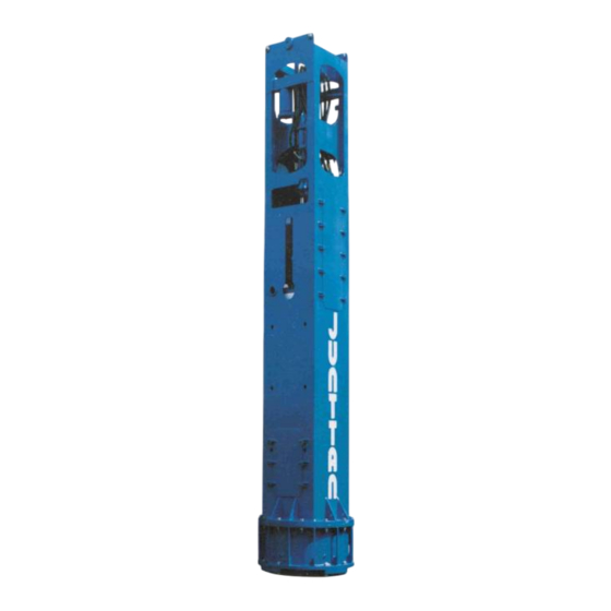
OPERATOR’S MANUAL TECHNICAL DESCRIPTION JUNTTAN HAMMER JUNTTAN hammer is a hydraulically-powered drop hammer for impact driving. The cage frame houses the components of the hammer. There are bolted wear pads on each corner of the ram block which slide along inside the frame uprights. -
Page 10: Specifications Section
SPECIFICATIONS SECTION • GENERAL IDENTIFICATION Type of the hammer: HHK 5/7SL Serial number: 21237 Name and address of manufacturer: Junttan Oy Matkuksentie 7 70800 Kuopio FINLAND Year of manufacture: 2011 Maximum theoretical characteristic of the hammer: Ram block weight (5/6SL): 5 000/6 000 kg (11 023/13 228 lb) Max. - Page 11 OPERATOR’S MANUAL HYDRAULIC ACCUMULATORS - pressure side (10 L) type: elastic bladder in steel case nitrogen pressure (5/6SL): 121/146 bar (1 755/2 118 psi)/20 °C - return side (4 L) type: elastic bladder in steel case nitrogen pressure: 6 bar/20 °C Pre-set pressure is stamped to accumulators.
- Page 12 OPERATOR’S MANUAL MAIN DIMENSIONS...
-
Page 13: Controls
OPERATOR’S MANUAL CONTROLS USB1 USB memory port Main current indicator (Power ON/OFF) Potentiometer for dwell time Potentiometer for drop height Power ON/OFF switch Emergency stop switch Piling mode switch, manual/continuous switch Short stroke switch Piling interruption button Pile depth measuring button Single lift/start piling button Single lift/start piling button Minimum oil flow switch... -
Page 14: Operating The Hammer
NOTICE! Junttan Oy recommends that the operator starts pile driving with small strokes because the cushion is more brittle under lower temperatures. After a few minutes the cushion is heated up and it is possible to use normal strokes. -
Page 15: Limitation Of Use Of The Piling Hammers
OPERATOR’S MANUAL LIMITATION OF USE OF THE PILING HAMMERS General As with all machinery there is a limit as to the operational conditions under which the machinery is expected to function safely, efficiently and longer lasting. A general definition for the piling hammers limit is described below. Limitation of use Under normal piling conditions, the hammer must be stopped when a 10 blows or more per 25 mm of penetration is recorded, over 6 consecutive... -
Page 16: Hammer Operation
OPERATOR’S MANUAL HAMMER OPERATION If the hammer is connected to the piling rig check the hammer operating instructions from the piling rig operator’s manual. • Check that there is no person in the hammer working area. • Check that the hammer is resting on a pile. •... -
Page 17: Manual Hammer Operation
OPERATOR’S MANUAL 6.3.1 MANUAL HAMMER OPERATION • Turn the piling mode switch (1) on the console to position 1 - manual driving. In this position the hammer hydraulic circuit is pressurized. • The pressure setting for the hammer used and the ram block is stated in the specifications manual of the hammer. -
Page 18: Continuous Hammer Operation
OPERATOR’S MANUAL 6.3.2 CONTINUOUS HAMMER OPERATION • Turn the drop height dial (3) to minimum and the dwell time (4) dial to maximum. • Turn the piling mode switch (1) to position 2. • To start continuous hammer operation, push the ram block single lift buttons (5) down simultaneously. -
Page 19: Lifting Of The Hammer
OPERATOR’S MANUAL LIFTING OF THE HAMMER Always use shackles when lifting the hammer. Fasten the ropes to the shackles (four pieces) and lift the hammer up. Know your dimensions and pay attention to the overhang in turns and corners. WARNING! Remove the shackles and ram block locking pin before start piling. -
Page 20: Function Of The Hammer
OPERATOR’S MANUAL FUNCTION OF THE HAMMER Lifting the ram block Solenoid valve changes the position of the spool valve so that the upper side of the piston is released to the tank line and the ram block is raised. Releasing the ram block The solenoid valve changes the position of the spool valve so that there is an equal pressure on both sides of the piston and the ram block falls down freely. -
Page 21: Permissible Operating Temperature Of The Accumulator
OPERATOR’S MANUAL 6.5.3 PERMISSIBLE OPERATING TEMPERATURE OF THE ACCUMULATOR The permissible operating temperature is determined by the material of the accumulator body, valve and bladder, and it is indicated on the type code label and the certificate of conformity. If the equipment is forwarded to different climatic conditions, the operator is responsible for ensuring compliance with the permissible operating temperature. -
Page 22: Field Maintenance And Repairs
OPERATOR’S MANUAL FIELD MAINTENANCE AND REPAIRS REPLACING THE DRIVE CAP CUSHION Replace the drive cap cushion when it is damaged due to heat, mechanically or worn out. To check the wear of the cushion dismount the drive cap. Before starting replacement of drive cap check that cushion is not hot because cooled cushion can be removed easier. -
Page 23: Dismounting Of The Drive Cap
OPERATOR’S MANUAL DISMOUNTING OF THE DRIVE CAP • Position the leader to vertical. • Lower the hammer onto wooden supports on ground. • Unscrew the nuts of the bottom ring (1). • Lift the hammer up and the drive cap and bottom ring remain on the ground. -
Page 24: Disconnecting The Cylinder From The Frame
OPERATOR’S MANUAL DISCONNECTING THE CYLINDER FROM THE FRAME You may need to remove the hammer lifting cylinder because of breakage or leakage. If you have a spare cylinder it is faster and better to remove the complete cylinder and to do the repair or service under more controlled circumstances. -
Page 25: Changing Of The Cylinder Seals
OPERATOR’S MANUAL CHANGING OF THE CYLINDER SEALS • Disassemble the cylinder in a clean environment. • Upper and lower parts seals can be changed without removing cylinder from the frame. • Clean the lifting ram with steam. • Record the lifting cylinder serial number, which is stamped to the upper part of the cylinder. - Page 26 OPERATOR’S MANUAL • Lower part: • Remove the four bolts (2). • Unscrew the cylinder eye (3). • Open the nuts (10). • Remove the seal housing (19) carefully. • Change the seals. • Check that shoulder of the seal (17 and 18) is towards to piston pressure side.
-
Page 27: Dismantling The Cylinder
OPERATOR’S MANUAL DISMANTLING THE CYLINDER • Connect the cylinder from the centre part (1) to a screw vice. • Prior to dismantling the cylinder check that the piston moves lightly full length of its stroke. • Remove the four bolts (2). •... -
Page 28: Inspecting The Cylinder
OPERATOR’S MANUAL INSPECTING THE CYLINDER • Check that there is no scratches etc. on the inside surface of the cylinder tube. • If you see mirroring on the inside surface check that the diameter meets the specification. • Measure the piston rod diameter in five equally space positions on each side of the piston position. -
Page 29: Assembling The Cylinder
OPERATOR’S MANUAL ASSEMBLING THE CYLINDER The main parts. All parts must be clean before assembling. Connect cylinder tube to a screw vice as shown in the picture. Needed special tools. A: tool for upper part seals B: tool for lower part seals C: tool for piston rod threads D: tool for piston seals 1. - Page 30 OPERATOR’S MANUAL Oil the parts and assemble the spool valve (6) to upper part as shown in the picture. The spool valve must be completely in vertical position because clearance between surfaces is so small. Fit the O-ring (7) to its groove and assemble the cover (1).
- Page 31 OPERATOR’S MANUAL Fit the support rings (9) and O-rings (10) to the upper and lower parts. Fit support rings so that O-ring is between them. Assemble lower and upper part seals. - 2 spacer rings (11 and 12) - 2 pressure seals (13+O-ring, 14) - wiper ring (15) Check the grooves of the seals before assembling.
- Page 32 OPERATOR’S MANUAL Check that shoulder of the seal (13 and 14) is towards to piston (pressure side). See picture beside. Gently tap the tools (A and B) through the holes to locate the seals into right positions. Assemble the piston seals as follows: Check the groove of the seals before assembling.
- Page 33 OPERATOR’S MANUAL Assemble the upper part (5) to the cylinder tube. Lock the upper part with four nuts (29) lightly. Use special washers (Nord-lock). Remove mounting tool (D) from piston. Lift the piston and push it inside the cylinder tube as shown in the picture.
- Page 34 OPERATOR’S MANUAL Screw the tool (C) onto the piston rod threaded end. Assemble the lower part (19) to its cylinder tube. Lock the lower part with four nuts (29) lightly. Use special washers (Nord- lock). Remove the tool (C) from the piston rod threaded end.
- Page 35 OPERATOR’S MANUAL Clean the threads of the lifting eye mounting plate (20). Screw on the lifting eye mounting plate (20) to the piston rod. Assemble the lifting eye (21) and lock it with four bolts (22). Torque up bolts equally crosswise. - pre-tighten bolts with a torque wrench to100 Nm (73 lbf-ft) - pre-tighten bolts with a torque...
- Page 36 OPERATOR’S MANUAL Check that both upper and lower parts are parallel. Torque up bolts and nuts equally and in sequence to: - return hose bolts (28) 190 Nm (140 lbf-ft) - upper and lower parts nuts (29) HHKA-cylinder 600 Nm (442 lbf-ft) HHK-cylinder 350 Nm (257 lbf-ft) Assemble the solenoid valve (30) to its place.
-
Page 37: Mounting Of The Top Plate
OPERATOR’S MANUAL MOUNTING OF THE TOP PLATE 1. Center top plate on the top of the ram block. 2. Attach screws to ram block. 3. Torque up screws equally and in the sequence. 4. Pre-tighten screws with a torque wrench to 100 Nm (73 lbf-ft). 5. -
Page 38: Piling Function Fault Detection
OPERATOR’S MANUAL PILING FUNCTION FAULT DETECTION The piling function fault detection is shown in the following diagram. Common faults 1. Piling cable 2. Valve Y48 3. Drop height proximity switch S29 (automatic piling mode) 4. Valve Y38 NOTICE! Only qualified personnel may do service actions. If possible use the piling tester to detect faults. - Page 39 Piling function fault detection Piling mode switch Is piling Is manual Piling mode switch (S33) Is delay Is drop height Ram block stroke irregular/no stroke (S33) in position 1, pressure in piling mode in position 2. Is automatic working? working? -check Y38 pressure settings/function is piling pressure set value?
-
Page 40: Lubrication
OPERATOR’S MANUAL LUBRICATION Grease hammer according to picture below. Use grease gun and brush. Recommended grease brands: Location Manufacturer Neste Mobil Esso Shell Castrol Teboil General greasing, Allrex EP2 Mobilgrease General Retinax LM Plus Multi-purpose bearings grease EP2, EPL 2 grease Guide claws, Molygrease... -
Page 41: Routine Service Chart Hammers
The accumulator must be relieved of pressure on the fluid side. After screwing on the charging/testing device and depressing the button, the pressure gauge indicates the pre-charge pressure. See hydraulic accumulator operations instructions. Consult Junttan Oy or special service company. -
Page 42: Torque For Steel Bolts And Nuts
OPERATOR’S MANUAL TORQUE FOR STEEL BOLTS AND NUTS Torque guidelines [Nm] Recommended torque figures below are based on tests in our own lab with calibrated torque transmitters and load cells. GF = ratio of yield point µg = thread friction µw = washer friction GTP600 = graphite lubricant ®... - Page 43 OPERATOR’S MANUAL Torque guidelines [Nm] Recommended torque figures below are based on tests in our own lab with calibrated torque transmitters and load cells. GF = ratio of yield point µg = thread friction µw = washer friction GTP600 = graphite lubricant ®...
- Page 44 OPERATOR’S MANUAL Torque guidelines [Nm] Recommended torque figures below are based on tests in our own lab with calibrated torque transmitters and load cells. GF = ratio of yield point µg = thread friction µw = washer friction GTP600 = graphite lubricant ®...
-
Page 45: Torque For Hydraulic Fittings
OPERATOR’S MANUAL TORQUE FOR HYDRAULIC FITTINGS Notice! Torque values are valid when threads are not lubricated before installation. METRIC Thread mm Lb.ft M12x1.5 M14x1.5 M16x1.5 M18x1.5 M20x1.5 M22x1.5 M24x1.5 M26x1.5 M30x2 M36x2 M42x2 M45x2 M52x2 SAE J514 37º Flare (JIC) Dash Thread Lb.ft...
Need help?
Do you have a question about the HHK 5/6SL and is the answer not in the manual?
Questions and answers
Можно ли использовать телескопический кран для работы с этим молотом?