Advertisement
Quick Links
Advertisement

Summary of Contents for VAMISOUND LDC84
- Page 1 LDC84 BUILDING INSTRUCTIONS...
- Page 2 LDC84 BUILDING INSTRUCTIONS Dear friend, first of all thank you for your support and choice of the VAMISOUND product. We wish you a happy DIY and the joy of a new microphone in your arsenal!! Jan and Milan...
- Page 3 Before you start building your new microphone please carefully read this building instructions. Attention: VAMISOUND LDC84 is a medium-heavy project. The circuit is made up of only a few components. However, it should be borne in mind that certain manual skills will be required or the successful completion of the mic construction.
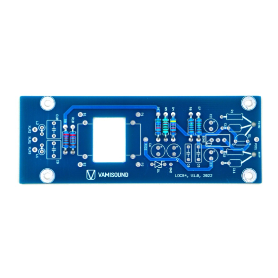
- Page 4 The VAMISOUND LDC84 circuit board allows you to build a microphone that is based on the circuitry from the legendary KM84 small diaphragm microphone. However, thanks to a small modification of the input section of circuit, it can use a large diaphragm capsule. The circuit is frequency flat, with no internal equalizer, so capsules like the C12, M7 or K47 fit perfectly with it.
- Page 5 Now solder resistors R1 and R2 with value 1G. Note that one leg of the resistors is always resting on the teflon pin and is as if in the air. Continue by soldering two inductors L1 and L2 and a zener diode D1.
- Page 6 The capacitors are next. Start with ceramic C1 and film ones. One leg of the C11 capacitor is connected to a teflon pin in the air. Note that the teflon pins have been shortened at the bottom.
- Page 7 Connect the Q1 FET transistor (or rather its GATE let) to the teflon pin. On the 2N3819 transistor, the GATE leg is the middle one. Always check the pin out of the transistor you are using against the datasheet.
- Page 8 Continue by installing the trimmer resistor. This trimmer will serve you later for the bias procedure. And now it's the turn of the three electrolytic capacitors. Do not install C3 if you will later use a PIO hi-end capacitor at the output capacitor position.
- Page 9 Clean the underside of the board thoroughly with iso propyl alcohol. Remove any residual flux and other contaminants. Also focus on cleaning the HiZ section around the two teflon pins. Now comes the fun! Installing the transformer. Use the remaining resistor legs to attach the transformer to the pcb.
- Page 10 Connect the wires of the transformer primary to the pads on the board which are labeled P1 (primaries start) and P2 (primaries end). Transformer secondary wires to pad S1 (secondaries start) and S2 (secondaries end). Do not shorten the wires too much, so that you will be able to swap them if necessary. Always check the phase of a finished microphone against a commercial microphone that you know has the phase right.
- Page 11 Make sure that the condenser does not touch the board to avoid unwanted contact causing a short circuit.
- Page 12 As you may have noticed the board offers two options for the output capacitor. You have a choice between a large PIO output capacitor that you install from the bottom of the board and a smaller capacitor that can be installed in the C3 footprint from the top component side of the board.
- Page 13 Screw the capsule holder to the plate using two screws. Screw the prepared plate to the rest of the BM90 body chassis.
- Page 14 Now screw the prepared XLR insert to the body and also the fitted circuit board. Solder the three cables to the appropriate pads on the board. XLR1 pin to XLR1 pad on the pcb, XLR2 pin to XLR2 pad and finally XLR3 pin to XLR3 pad.
- Page 15 Next comes the installation of the capsule. Take extra care during this process and always wear fitted gloves (powder free).
- Page 16 Screw the capsule carefully to the holder using the two screws and put the protective bag on the capsule. This will serve to protect you from any potential hazards caused by soldering the cable to the capsule. Very carefully solder the red wire to the front diaphragm. Then the white wire to the backplate.
- Page 17 Solder the other end of the red wire to the teflon pin marked "FD". Solder the other end of the white wire to the second teflon pin. It is marked "BCKP". Now the capsule is connected to the circuit. Put the head basket on to protect the capsule.
- Page 18 Now the only last step to complete your new microphone is calibration. It is necessary to bias the FET transistor. Bias procedure: 1) Connect the microphone to your favorite preamp with the cable and activate the phantom power on the preamp.
-
Page 20: Additional Info
WIRRING INFO 1) Capsule wiring: Front membrane cable to teflon pin marked as „FD“ from the bottom side of pcb. Cable from capsule backplate to „BCKP“ pad on the mic pcb. 2) Its always great idea to check phase of DIY microphone against commercial microphone. ADDITIONAL INFO Take you time when soldering the XLR insert. -
Page 21: Bill Of Material
BILL OF MATERIAL Part Value Tol. Min.V Dimmensions link 1 link 2 notes olt. Resistors 10 % 6.5x2.5mm mouser link 10 % 6.5x2.5mm mouser link 20 % mouser link trimmer mouser link mouser link mouser link mouser link mouser link 2K21 mouser link matched to R10... - Page 22 Part Value Tol. Min.V Dimmensions link type notes olt. Diodes mouser link Inductors 47uH mouser link 47uH mouser link Tranzistors 2N3819 mouser link Other CTS-12, Maiku C12, K47, 3U Audio C12, K47, M7 Capsule Teflon pin mouser link Transformer 3U Audio GTZ-84, Moby BV.107 (not compatiable with pcb transformer hole) Mic body BM90 from Alibaba or Aliexpress...