
Summary of Contents for KISTERS HyQuest Solutions VHPS SDI-12
- Page 1 Vented Hydrostatic Pressure Sensor (VHPS): User’s Manual HyQuest Solutions -KISTERS Group- 06 JUNE 2020...
- Page 2 Revision Sheet Release No. Date Revision Description 23 June 2020 First Release 200615_HS_USER MANUAL-VHPS-FINAL.DOCX Page 2 / 22...
-
Page 3: Table Of Contents
Content SAFETY INSTRUCTIONS ..................... 6 INTRODUCTION ......................7 TECHNICAL DATA ...................... 7 SDI-12 DATA TRANSFER INTERFACE ................8 Description ......................... 8 SDI-12 Command Set ......................8 4.2.1 Data Logger/Controller Commands and Sensor Responses ............8 4.2.1.1 Break .............................. 9 4.2.1.2 Acknowledge Active ........................ - Page 4 4.2.3.11 Saving settings in flash memory ....................18 RECALIBRATION ...................... 18 Zero-point pressure recalibration ..................18 Nominal pressure recalibration ..................19 Zero-point and nominal pressure recalibration ..............20 UNIT CONVERSION ....................21 CONTACT DATA ...................... 22 Australia ........................... 22 New Zealand ........................22 Europe ..........................
- Page 5 Glossary ACRONYM Description SI unit symbol for “Ampere”, physical unit for electrical current ASCII American Standard Code for Information Interchange Data Byte Data Word SI unit symbol for “millimetre”, metrical system Pressure Nominal pressure Zero-point pressure International System of Units Temperature End of temperature range Start of temperature range...
-
Page 6: Safety Instructions
Safety Instructions • Read the user manual including all operating instructions prior to installing, connecting and pow- ering up the HyQuest Solutions VHPS. The manual provides information on how to operate the sensor system. The manual is intended to be used by qualified personnel, i.e. personnel that has been adequately trained, is sufficiently familiar with installation, mounting, wiring, powering up and operation of radar sensors. -
Page 7: Introduction
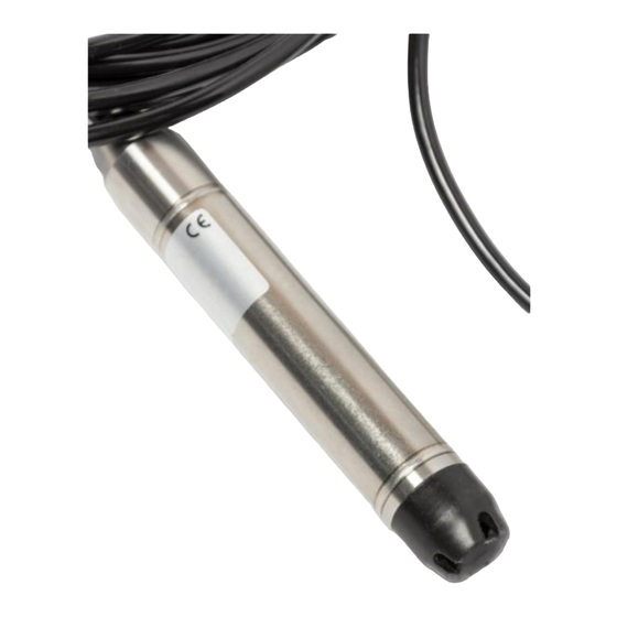
Introduction Thank you for opting for HyQuest Solutions’ Vented Hydrostatic Pressure Sensor (VHPS)! The VHPS SDI-12 provides the following functions: • Zero-point and nominal pressure recalibration • SDI-12 interface • Pressure units selectable • Temperature units selectable • Additional identification string Vented Hydrostatic Pressure Sensors are typically used to measure water levels in running or standing water bodies. -
Page 8: Sdi-12 Data Transfer Interface
SDI-12 Data Transfer Interface Table 2 – SDI-12 Interface Specs Protocol SDI-12, Version 1.3 Default Address 0 (factory settings) Transfer Rate 1200 baud Start Bits Data bits Parity 1 bit, even Stop Bit Description SDI-12 is a standard for interfacing data recorders with microprocessor-based sensors. SDI-12 stands for serial/digital interface at 1200 baud. -
Page 9: Break
• the sensor address – denoted ‘a’ with a value range [0 … 9, A … Z, a … z] • the character "!" terminates the command • most commands have a command character Caution: The address character "?" can only be used if only a single sensor is connected to the physical SDI-12 bus. -
Page 10: Address Query Command (?!)
• Response: 0<CR><LF> 4.2.1.4 Address Query Command (?!) This command queries the sensor address. Using the generic ‘?’ address, forces all sensors connected to the bus to respond. It must be noted that if more than a single sensor is connected to the bus, they will all respond, causing a bus contention. -
Page 11: Extended Measurements Command
• Command: 0M1! (start measurement) • Response: 00011<CR><LF> (2 measurements ready in 1 second) • Response: 0<CR><LF> (Service Request) • Command: 0D0! (send data) • Response: 0+0.012<CR><LF> (e.g. +0.012bar) • Command: 0M2! (start measurement) • Response: 00011<CR><LF> (2 measurements ready in 1 second) •... -
Page 12: Service Request (From Sensor To Data Logger)
• ttt == time in seconds until measuring results are available • n == no. of measured results/readings o n = 1 (one pressure or one temperature measured value) • ccc CRC-16 checksum (3 characters) The commands aM3!..aM9! and aMC3!..aMC9! are implemented, even though they do not result in any meaningful information. -
Page 13: 4.2.1.10 Additional Concurrent Measurements Command
where: • sensor address (0, 1..9, A..Z, a..z) Sending the “D” command to pick up the data is not necessary but allowed. The response after a “D” command is always a<CR><LF> 4.2.1.10 Additional Concurrent Measurements Command Measurements can be triggered in several sensors with this command. It starts a measurement in the sensor, while another sensor is still busy with its measurements (also "C"... -
Page 14: Crc-16 Checksum
• Command: aRC0...aRC9! Requesting of measured values with CRC-16 checksum • Response: accc<CR><LF> where: • sensor address (0, 1..9, A..Z, a..z) • CRC-16 checksum (3 characters) 4.2.2 CRC-16 Checksum • Details see SDI-12 standard V1.3 chapter 4.4.12 4.2.3 SDI-12 extended commands This chapter describes extended commands which extend the standard command set. -
Page 15: Reading Pressure Unit
• Response: 001<CR><LF> (index of unit 01 = bar) 4.2.3.2 Reading pressure unit Causes the sensor to output the selected unit. • Command: aXP! • Response: ann<CR><LF> where: • sensor address (0, 1..9, A..Z, a..z) • index of unit (see table below) Table 4 - Table of units: Index Unit Index Unit... -
Page 16: Setting Recalibration Value Of Nominal Pressure
• <value> recalibration value in the adjusted unit (max. 8 characters including sign) 4.2.3.5 Setting recalibration value of nominal pressure Use this command for recalibration of nominal pressure or reset the nominal pressure recalibration to default. The recalibration value <value> has to be in the adjusted unit. For reset to default set the recali- bration value to default nominal pressure in the actually adjusted unit. -
Page 17: Reading Temperature Unit
°F Settings made by extended commands are volatile and not automatically saved. For permanent storage use the save command (see 4.2.3.11). Caution: Settings must be explicitly saved to avoid loss during power up.. Example setting temperature unit Initial condition: address: 0 unit: °C •... -
Page 18: 4.2.3.10 Reading User Identification String
4.2.3.10 Reading user identification string Reads the identification string of the sensor. The identification string has a maximum length of 16 charac- ters. • Command: aXI! • Response: a<string><CR><LF> where: • sensor address (0, 1..9, A..Z, a..z) • <string> identification string (1..16 printable characters) 4.2.3.11 Saving settings in flash memory Causes the sensor to save all settings in the internal flash memory. -
Page 19: Nominal Pressure Recalibration
6. Write the recalibration value to the sensor (see 4.2.3.3) 7. Set zero-point reference pressure 8. Read out the pressure from the sensor (with “M” and “D” Command) 9. Calculate the error (repeat procedure if necessary) 10. Save the recalibration value (see 4.2.3.11) Calculation of zero-point pressure recalibration value Nominal pressure recalibration 1. -
Page 20: Zero-Point And Nominal Pressure Recalibration
10. Save the recalibration value (see 4.2.3.11) Calculation of nominal pressure recalibration value Zero-point and nominal pressure recalibration 1. Read out the actual recalibration value of nominal pressure -> PUserCalFullscale (see 4.2.3.6) 2. Read out the actual recalibration value of zero-point pressure -> PUserCalZero (see 4.2.3.4) 3. -
Page 21: Unit Conversion
Calculation of zero-point and nominal recalibration value Unit conversion Table 7 – Pressure Unit Conversion Table Unit mbar mWC / mH2O ftWC inH2O 1000 10.1968 14.5033 33.456 401.606 mbar 0.001 0.0101968 0.014503 0.033456 0.401606 mWC / mH2O 0.09807 98.07 1.422338 3.281299 39.38550 0.06895... -
Page 22: Contact Data
| +49 2408 9385 0 | info@hyquestsolutions.eu Latin America HyQuest Solutions (KISTERS LATAM) | +57 323 585 5963 | sales-latam@hyquestsolutions.com North America HyQuest Solutions (KISTERS North America, Inc.) | +1 916 723 1441 | sales-us@hyquestsolutions.com 200615_HS_USER MANUAL-VHPS-FINAL.DOCX Page 22 / 22...
Need help?
Do you have a question about the HyQuest Solutions VHPS SDI-12 and is the answer not in the manual?
Questions and answers