Table of Contents
Advertisement
INSTALLATION MANUAL
AIR HANDLER UNIT: 30K to 60K
DRAM30S1A, DRAM36S1A, DRAM48S1A, DRAM60S1A
208/230V 1ph 60 HZ 24V / RS485 Communicating
Model Number:
Serial Number:
Purchase Date:
Installing Contractor Company Name:
NOTE
This manual only refers to the models listed above. If you are installing the DRAM18F1A or
DRAM24F1A please refer to the manual included with that unit.
TIP
Capture relevant information about your Durastar mini-split equipment before it is
installed and write it above for future reference.
1
R
DURASTAR.COM
Advertisement
Table of Contents

Related Manuals for DURASTAR DRAM30S1A


Summary of Contents for DURASTAR DRAM30S1A
- Page 1 This manual only refers to the models listed above. If you are installing the DRAM18F1A or DRAM24F1A please refer to the manual included with that unit. Capture relevant information about your Durastar mini-split equipment before it is installed and write it above for future reference.
-
Page 2: Table Of Contents
CONTROL LOGIC ............................. 36 LED DISPLAY DEFINITIONS ........................38 DIP SWITCHES SETTINGS ........................... 39 AIR VOLUME TABLE ............................42 POWER SPECIFICATIONS ........................... 46 FINAL CHECKS ..............................47 TEST RUN ................................48 WIRING DIAGRAM .............................52 ERROR AND OPERATING CODES ......................53 DURASTAR.COM... -
Page 3: Introduction
• Read the troubleshooting section of this manual as it will help you diagnose and solve common issues. • Visit us on the web at www.durastar.com to download product guides and up-to-date information. • If you need warranty service, our friendly customer service representatives are available via email at questions@durastar.com or by telephone at 1-888-320-0706. -
Page 4: Important Safety Precautions
• In certain environments, such as kitchens, server rooms, etc., the use of specially designed air- conditioning units is highly recommended. • As with any mechanical equipment, contact with sharp sheet metal edges can result in personal injury. Take care while handling this equipment and wear gloves and protective clothing. DURASTAR.COM... - Page 5 The airflow decreases below 0.80 in WC or 200Pa. System design should allow for the increased resistance as filters become dirty. The data below represents the static pressures at full required air flow used for AHRI testing. 18-24k: 0.5 in-H2O(125Pa) 30-36k: 0.5 in-H2O(125Pa) 48-60k: 0.5 in-H2O(125Pa) DURASTAR.COM...
-
Page 6: Operating Temperatures
To further optimize the performance of your unit, do the following: • Keep doors and windows closed. • Limit energy usage by using TIMER ON and TIMER OFF features. • Do not block air inlets or outlets. • Regularly inspect and clean air filters. DURASTAR.COM... -
Page 7: Accessories
Drain Fitting Gasket NOTE The Durastar wired control (DRSTAT100) functions as an IR receiver for the handheld remote. If the remote is not used, it must be retained with the indoor unit to adjust parameters and for troubleshooting. FIELD SUPPLIED INSTALLATION ACCESSORIES The following installation accessories are required and must be purchased separately. -
Page 8: Unit Dimensions
A (Height) B (Depth) C (Width) in (mm) in (mm) in (mm) in (mm) in (mm) 19-5/16 10-1/4 30K - 48K 49 (1245) 21 (533) 21 (533) (490) (260) 24-1/2 22-7/8 10-1/4 53 (1346) 21 (533) (622) (580) (260) DURASTAR.COM... -
Page 9: Filter Size
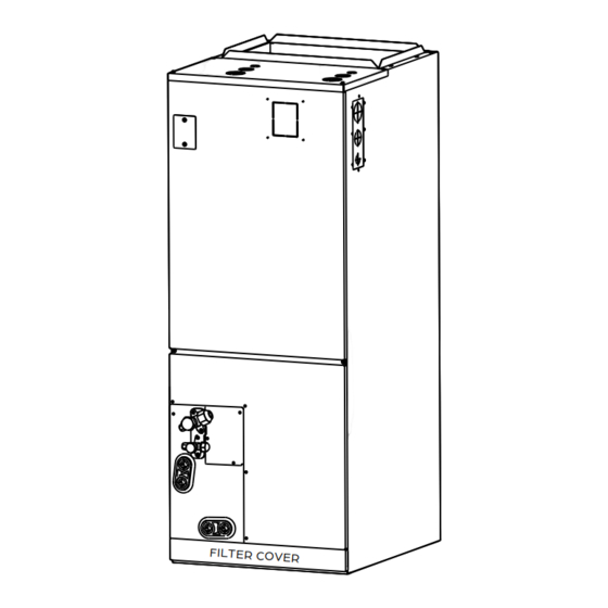
Blower Fan and Motor Suction Line Liquid Line Evaporator Horizontal Drain Vertical Drain Filter and Filter Cover (not shown) Air Inlet NOTE Illustrations in this manual are for explanatory purposes. The actual shape of your equipment may vary slightly. DURASTAR.COM... -
Page 10: Installation Preparation
• Areas where the air inlet or outlet of the indoor or outdoor unit may be obstructed. NOTE In addition, you must be aware of needed clearance space, installation direction, and duct requirements. These items are covered in the following pages. DURASTAR.COM... - Page 11 Horizontal installations The outlet side pipe length 59”/1.5m. Vertical Installations When installed vertically (upward or downward), the lower end of the air outlet needs to be connected to the L-shaped metal air duct and fastened by screws. Vertical installations DURASTAR.COM...
- Page 12 At least 3in(76mm) Make sure wiring Vertical up Horizontal is not laying in the pan. Airflow Direction Horizontal left Horizontal right Upflow Downflow NOTE Vertical up and horizontal left installations do not need to change the direction of the evaporator. DURASTAR.COM...
- Page 13 STEP 1. REMOVE THE FILTER STEP 2. REMOVE THE UPPER COVER Remove the filter door, then take the filter out. STEP 3. REMOVE THE EVAPORATOR COVER PLATE Remove the bottom cover first, then remove the cover plate. cover plate bottom cover DURASTAR.COM...
- Page 14 T2A&T2B STEP 5. UNLATCH THE ADJUSTABLE WIRE TIES ON THE T1, T2, T2A, T2B AND EEV SENSOR CABLES. Cut wire ties clamping wires to the coil as necessary to give slack. 30-48k Units 60k Units 30-48K model 60K model DURASTAR.COM...
- Page 15 STEP 6. REMOVE THE EVAPORATOR AND DRAIN PAN. STEP 7. ADJUST THE MOUNTING BRACKET TO THE PRE-DRILLED HOLES ON THE LEFT SIDE OF THE CABINET. DURASTAR.COM...
- Page 16 Cut the foam gasket. Remove knockouts as shown in the figure. Hook the wire into the buckle and go down from the wire slot. Replace foam gasket over wires. DURASTAR.COM...
- Page 17 THE PIPES ON THE TOP OF THE EVAPORATOR. Leave the sensor overhanging enough to not be affected by the temperature of the pipe. cable ties STEP 11. REINSTALL THE EVAPORATOR AND FILTER COVER PLATES. Place unit into desired downflow or horizontal right position. DURASTAR.COM...
-
Page 18: Air Handler Installation
STEP 3: IF INSTALLING AN OPTIONAL AUXILIARY ELECTRIC HEATER, REFER TO THE HEATER INSTALLATION SECTION FOR WIRING DIAGRAMS AND EXPLANATION. STEP 4: INSTALL OPTIONAL DEVICES. STEP 5: CHECK AIR FLOW AND PERFORM A TEST RUN. Electrical Control Box Upper Cover Suction Line Liquid Line Horizontal Drains Vertical Drains DURASTAR.COM... -
Page 19: Duct Requirements
There must be an airtight seal between the bottom of the air handler and the return air plenum. Use fiberglass sealing strips, foil duct tape, caulking, or an equivalent sealing method between the plenum and the air handler cabinet to ensure a tight seal. DURASTAR.COM... -
Page 20: Condensate Piping Installation
The drain pan must be installed under the entire unit and its condensate drain line must be routed to a location such that the user will see the condensate discharge. For horizontal installations, a secondary drain pan-not supplied-must be installed. DURASTAR.COM... - Page 21 Drain Anti-syphon Vent Vent T Angle Down 1/50 Drain Trap WARNING The drainpipe outlet should be at least 1.9" above the ground or anticipated snowfall line. If it touches the ground, the drain may become blocked. DURASTAR.COM...
-
Page 22: Refrigerant Piping Connection
3/8 x 3/4 25 (7.6) 0.69 (65) 213 (65) 98.4 (30) 3/8 x7/8 25 (7.6) 0.69 (65) 213 (65) 98.4 (30) NOTE Adapters are included with the indoor unit and outdoor unit to convert the flared fittings to brazed if necessary. DURASTAR.COM... - Page 23 Indoor unit/ Outdoor unit Suction Line Oil Trap Unit < 36k then 20ft (6m) Unit > 36k then 32ft (10m) Liquid Line Indoor unit/ Outdoor unit Unit < 36k then 20ft (6m) Unit > 36k then 32ft (10m) DURASTAR.COM...
- Page 24 1. After removing burrs from cut pipe, seal the ends with PVC tape to prevent foreign materials from entering the pipe. 2. Sheath pipe with insulating material. 3. Place flare nuts on both ends of the pipe. Make sure they are facing in the right direction as you cannot change their orientation after flaring. DURASTAR.COM...
- Page 25 6. Place flaring tool onto the form. 7. Turn the handle of the flaring tool clockwise until the pipe is fully flared. 8. Remove the flaring tool and flare form, then inspect the pipe for cracks and even flaring. DURASTAR.COM...
- Page 26 4. Using a wrench, grip the nut on the unit tubing. 5. While firmly gripping the nut on the unit tubing, use a torque wrench to tighten the flare nut according to the torque values in the table in Step 3. Loosen the flaring nut slightly, then tighten again. DURASTAR.COM...
- Page 27 Check to make sure there is no refrigerant leak after completing the installation work. If there is a refrigerant leak, ventilate the area immediately and evacuate the system (refer to the air evacuation section of the outdoor unit manual). Foam Tape Braze Connection Flare Connection DURASTAR.COM...
-
Page 28: Wiring Overview
Do not install if any items are damaged. • Durastar factory approved heaters are UL rated with the equipment. DO NOT install a non-approved heater, this can cause damage and will not be covered under warranty. -
Page 29: Auxiliary Heater Electrical Data
AUXILIARY HEATER COMPATIBILITY CHART MODEL DRHTR05BRKA DRHTR08BRKA DRHTR10BRKA DRHTR15BRKA (Btu/h) 10kW 15kW DRAM30S1A (30k) DRAM36S1A (36k) DRAM48S1A (48k) DRAM60S1A (60k) AUXILIARY HEATER ELECTRICAL DATA INSTALLATION STEPS STEP 1: Open the upper cover. STEP 2: Remove the knock-out hole of the upper cover. - Page 30 Top View STEP 5: Tighten the mounting screws. Screws screws STEP 6: Connect the wiring according to the wiring diagram on page 32. Attach the wiring diagram sticker provided to the inside of the front cover for future reference. DURASTAR.COM...
-
Page 31: Confirm Electric Heater Wiring
Only use copper wire to connect the unit. If wire other than uncoated (non-plated) 75°C copper wire (solid wire for 10 AWG and smaller, stranded wire for larger than 10 AWG) is used, consult applicable tables of the National Electric Code (ANSI/NFPA 70). DURASTAR.COM... -
Page 32: Electric Auxiliary Heating Wiring Diagrams
AHU; for type A, S position must be connected to the RELAY 1 RELAY 1 ourdoor S; for type B, S position shall not be connected. RELAY 2 RELAY 2 1(L1) 2(L2) 3(S) RELAY 4 TYPE A TYPE B DURASTAR.COM... -
Page 33: Indoor Unit Wiring
• Match the wire colors/labels with the labels on the terminal block. Firmly screw the wires of each wire to its corresponding terminal. Refer to the Serial Number and Wiring Diagram located on the cover of the electric control box. DURASTAR.COM... - Page 34 In the event of unexpected failure, the SW1 can be switched according to connection methods 1, 2,and 3. Default Indoor Unit WARNING DO NOT connect 24VAC to the S1/S2 terminals. This will damage the system. Only connect to Class 2 terminals. DURASTAR.COM...
- Page 35 Use this method for full 24V communication. Refer to 24V wiring methods on page 39 depending on your application. Note: S1-2 must be flipped on at the outdoor unit. Note: Outdoor 24V Connection Indoor DO NOT WIRE!! Unit SW1 S2 B W D R C Y1 Y2 L TO 24V THERMOSTAT DURASTAR.COM...
-
Page 36: Control Logic
Stage 1 Electric Heating Stage 2 Electric Heating E/AUX Emergency Heating DH/DS/BK Dehumidification/Zoning Control System Fault Signal Outdoor Unit Connector CONNECTOR PURPOSE 24v Power Connection Common Low Cooling High Cooling Heating Reversing Valve Heating Control Defrost Control System Fault Signal DURASTAR.COM... - Page 37 Wiring for 2H and 2C Thermostat Wiring for 2H and 1C Thermostat S4-1 Defaults ON: W1 and W2 set for single stage Aux heat. Turn OFF to separate stages. Wiring for 1H and 1C Thermostat Wiring for 1H and 1C Thermostat DURASTAR.COM...
-
Page 38: Led Display Definitions
Heat Pump Stage 2 + Electric Turbo Heater Kit 1 and Kit 2 Emergency Heat Turbo Heating Zone Control Heating Zone Control Heating Zone Control Heating Zone Control Heating Zone Control Heating Zone Control Note: 1 = 24V Signal 0 = No 24V Signal DURASTAR.COM... -
Page 39: Dip Switches Settings
DIP Switch Interface Function DIP Switch Static Pressure DIP Switch Use the following two charts to make any necessary dip switch changes based on the chosen control scenario. 24V Tstat, S1+S2 Control DRSTAT100 Wired Controller, S1+S2 Scenario Full 24V DURASTAR.COM... - Page 40 For dual stage [Default] For single supplemental heat, stage supplemental S4-1 Default ON W1 and W2 are heat, W1 and W2 are controlled connected independently. Dehumidification [Default] feature is enabled S4-2 DH function selection Dehumidification through control not available thermostat DURASTAR.COM...
- Page 41 When using a 24V thermostat, use the SW4 dip switch to set the proper air flow and heater settings. 000 is the default SW4-1 Can be set as SW4-2 000/001/010/ 011/100/101/110/111, for electric heating and PSC classification SW4-3 depending on the unit. DURASTAR.COM...
-
Page 42: Air Volume Table
Kit 1 SW4-3=ON SW4-3=ON SW4-1=OFF SW4-1=OFF Electric Heater W1, W2, Heat + AUX, 10kW, 8kW SW4-2=ON SW4-2=ON 1176 Kit 2 SW4-3=OFF SW4-3=OFF SW4-1=OFF SW4-1=OFF Electric Heater W1, W2, Heat + AUX, 5kW, 8KW SW4-2=ON SW4-2=ON 1112 Kit 3 SW4-3=ON SW4-3=ON DURASTAR.COM... - Page 43 Kit 1 20kW SW4-3=ON SW4-3=ON SW4-1=OFF SW4-1=OFF Electric Heater 10kW, W1, W2, Heat + AUX, SW4-2=ON SW4-2=ON 1894 Kit 2 15KkW SW4-3=OFF SW4-3=OFF SW4-1=OFF SW4-1=OFF Electric Heater W1, W2, Heat + AUX, 10kW SW4-2=ON SW4-2=ON 1753 Kit 3 SW4-3=ON SW4-3=ON DURASTAR.COM...
- Page 44 An alarm output (CN33) can be utilized if actions are required when a fault is present. This is a passive outlet port, so you will need to input a voltage signal. The relay is normally-open for normal operation, and closed when a fault condition is active. DURASTAR.COM...
- Page 45 UV LED Wiring The WORK port is linked with the fan. When the fan is running, the relay is closed; if an active 24V signal is required, it can be directly connected to the G and C ports. DURASTAR.COM...
-
Page 46: Power Specifications
While connecting the wires, strictly follow the wiring diagram, and refer to the nameplate for electrical information. Wire according to NEC and local codes. Indoor Units Without Electric Heat Model Number MCA (A) MOCP (A) Volts-Phase Motor HP FLA (A) DRAM30S1A 208/230-1 DRAM36S1A 208/230-1 DRAM48S1A 208/230-1 DRAM60S1A 208/230-1 Outdoor Units... -
Page 47: Final Checks
1. Soap and Water Method - Using a soft brush, apply a soapy water or liquid detergent to all pipe connection points on the indoor and outdoor unit. The presence of bubbles indicates a leak. 2. Leak Detector Method - If using a leak detector, refer to the device's operation manual for proper usage instructions. DURASTAR.COM... -
Page 48: Test Run
6. Ensure the condensate flows smoothly through the drain. It may take up to one (1) minute before the unit begins to drain, depending on the drainpipe. In new buildings, this should be performed before finishing the ceiling. DURASTAR.COM... - Page 49 This noise is normal and is caused by the refrigerant gas and outdoor unit make stopping or changing direction. noises Squeaking sound: Normal expansion and contraction of plastic and met- al parts caused by temperature changes during operation can cause squeaking noises. DURASTAR.COM...
- Page 50 • Press ON/OFF button on remote control to restart operation. NOTE If problem persists, contact a local dealer or your nearest customer service center. Provide them with a detailed description of the unit malfunction as well as your model number. DURASTAR.COM...
- Page 51 Wait three minutes after restarting the been activated unit Timer is activated Turn timer off NOTE If your problem persists after performing the checks and diagnostics above, or an error code remains, turn off your unit immediately and contact an authorized service center. DURASTAR.COM...
-
Page 52: Wiring Diagram
WIRING DIAGRAM 30K, 36K, 48K, 60K DURASTAR.COM... -
Page 53: Error And Operating Codes
Top temperature protection of compressor or High temperature protection of IPM PC 02 module PC 03 Low pressure protection (for some models) PC 04 Inverter compressor drive error EC 0d Outdoor unit malfunction PC 0L Low ambient temperature protection FL 09 Mismatch between the new and old platforms DURASTAR.COM... - Page 54 THIS PAGE INTENTIONALLY LEFT BLANK. DURASTAR.COM...
- Page 55 THIS PAGE INTENTIONALLY LEFT BLANK. DURASTAR.COM...
- Page 56 THIS PAGE INTENTIONALLY LEFT BLANK. DURASTAR.COM ©2023 Durastar V1.0 0923...
Need help?
Do you have a question about the DRAM30S1A and is the answer not in the manual?
Questions and answers