
Related Manuals for MIMAC SUPREMA PLUS

Summary of Contents for MIMAC SUPREMA PLUS
- Page 1 SUPREMA PLUS SUPREMA MINIDROP PLUS MINIDROP USE AND MAINTENANCE MANUAL S/N: Date: Rev.:...
-
Page 3: Table Of Contents
3.3.1. FIXED GUARDS ............................11 3.3.2. MOVABLE GUARDS ..........................11 3.4. PLACEMENT OF SECURITY DEVICES AND SIGNALS ................11 3.4.1. SUPREMA / SUPREMA PLUS ........................11 3.4.2. MINIDROP / MINIDROP PLUS ......................... 12 3.5. RESIDUAL RISKS ............................12 4. MACHINE DESCRIPTION ............................. 13 4.1. - Page 4 4.4. MAIN COMPONENTS ............................. 15 4.5. EQUIPMENT ..............................15 4.6. WORKING AREAS ............................16 4.6.1. SUPREMA / SUPREMA PLUS ......................... 16 4.6.2. MINIDROP / MINIDROP PLUS ......................... 16 4.7. PRODUCTS OVERVIEW ..........................17 5. START-UP AND OPERATION CHECKS ......................18 5.1.
- Page 5 6.8.16. FLAME-SHAPED PRODUCT ........................41 6.8.17. MULTILAYER FIXED PRODUCT WITH ROTATION ................42 6.8.18. MULTILAYER LONG PRODUCT WITH ROTATION ................43 6.8.19. FLAME-SHAPED PRODUCT WITH ROTATION ..................44 6.9. WARNINGS ON PROGRAMMING ........................45 6.10. STARTING PRODUCTION ..........................45 6.10.1. PLACE THE DOUGH IN THE HOPPER ....................45 6.10.2.
- Page 6 www.mimac.com...
-
Page 7: Introduction
1. INTRODUCTION 1.1. OWNERSHIP OF THE MANUAL This manual belongs exclusively to MIMAC ITALIA SRL. Reproduction, even partial, is forbidden unless authorized by the Manufacturer. 1.2. PURPOSE OF THE MANUAL The aim of this manual is to provide information necessary for the correct and safe use of the machine and for carrying out operation as contemplated in the design phase. -
Page 8: Preliminary Information
If in the unquestionable opinion of our technicians it is not possible to intervene in the customer’s premises, the customer shall send the machine on DDP terms to MIMAC ITALIA who, after repairing the faulty part at no charge, shall return the machine on ex works terms. -
Page 9: Preparation Of The Work Places
The software cannot be altered, modified, copied and/or reproduced without written authorisation from MIMAC ITALIA. Being the owner of the software used to run its machines, MIMAC ITALIA will not grant the source codes of its software for any reason and will persecute anyone or anything that copies, reproduces, decodes or modifies the same software. -
Page 10: Users Training
Customer. It is forbidden to use the machine in conditions or for purposes other than those indicated in the manual and MIMAC ITALIA cannot be held responsible for faults or accidents caused by the non-observance of this rule. -
Page 11: Noise Warnings
To guarantee maximum working reliability, MIMAC ITALIA has accurately chosen the materials and components used to produce the apparatus, which was accurately tested before delivery. Good machine performance over time also depends on correct use and suitable maintenance in line with the instructions given in this manual. -
Page 12: Safety
ATTENTION! Machine moving parts in action BE CAREFUL to your hands DO NOT remove safety devices DO NOT clean, grease or adjust the machine elements while they are in action DO NOT clean the machine using water jets ATTENTION! Hand crush hazard www.mimac.com... -
Page 13: Description Of Safety Devices
They are connected to safety micro-switches or photocells meant for cutting in automatically whenever the covers are opened. The machine can start production again when the movable guards are closed. 3.4. PLACEMENT OF SECURITY DEVICES AND SIGNALS 3.4.1. SUPREMA / SUPREMA PLUS 1. Hopper movable guard 2. Wire-cut device movable guard 3. -
Page 14: Minidrop / Minidrop Plus
6. Information plate 3.5. RESIDUAL RISKS While using the machine for production or maintenance, the residual risks present are possible crushing of the hands between the die and the conveyor or between the die and the tray positioned above the conveyor. www.mimac.com... -
Page 15: Machine Description
In each machine there is an identification plate containing information about the Manufacturer and the machine (model name, serial number, power supply, year of manufacture). 4.3. TECHNICAL SPECIFICATIONS 4.3.1. SUPREMA / SUPREMA PLUS SUPREMA 400 SUPREMA 450 SUPREMA PLUS 400... -
Page 16: Minidrop / Minidrop Plus
MINIDROP PLUS 450 Dimensioni 840 mm 890 mm 1110 mm 1110 mm 1360 mm 1360 mm Peso 190 kg 195 kg Capacità tramoggia 24 lt 27 lt Alimentazione 200-240 V - 50/60 Hz - 1ph Dimensione teglie 400x600 mm 450x660 mm www.mimac.com... -
Page 17: Main Components
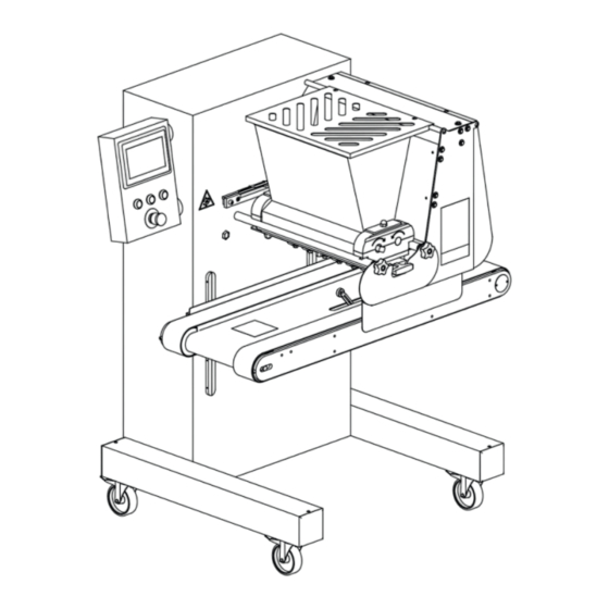
4.4. MAIN COMPONENTS 1 - Frame The frame is made of steel, aluminum alloy and stainless steel, covered by stainless steel panels that are fast and easy to clean and sanitize. 2 - Conveyor The conveyor allows the tray to move forwards or backward for an accurate placement and for moving while the machine is dropping. -
Page 18: Working Areas
4.6. WORKING AREAS 4.6.1. SUPREMA / SUPREMA PLUS Normal running direction The machine can be used by one operator only, who fills the hopper, feeds the trays and removes them. 1. Hopper filling area 2. Tray feeding area 3. Tray removing area and control panel 4.6.2. -
Page 19: Products Overview
Flame shaped product Multilayer fixed product with rotation Multilayer long product with rotation Flame shaped product with rotation (1) Available on SUPREMA and SUPREMA PLUS models only (2) Available on MINIDROP PLUS and SUPREMA PLUS models only USE AND MAINTENANCE MANUAL... -
Page 20: Start-Up And Operation Checks
The operator has a stop push-button to stop the machine, in addition to an emergency stop push-button and safety devices on the safety guards. Press the stop push-button to stop production temporarily. In danger situations, use the emergency stop push-button to immediately stop the machine. www.mimac.com... -
Page 21: Main Switch
Description Colour Function Touch screen panel Programming / selection of the product to be made Enabling push-button Blue Enables the machine to start production Stop push-button Interrupts the production cycle Start push-button Green Starts the production cycle Emergency stop push-button Red/Yellow Stops the machine in an emergency Flash drive connection for program backup/resetting and... -
Page 22: Preliminary Operations
3. Carefully push the dosing group towards the structure, aligning the motor roller with the relative 4. Insert the upper section of the head supports coupling 5. Insert the hopper and fasten it using the relative stop 6. Close the hopper guard nuts www.mimac.com... -
Page 23: Inserting The Pump Type Dosing Unit
5.4.2. INSERTING THE PUMP TYPE DOSING UNIT 1. Lay the head on the supporting rods 2. Delicately insert the two rollers into the cavity 4. Carefully push the dosing group towards the 3. Position the front cap and fasten it using the relative structure, aligning the motor roller with the relative stop nuts coupling... -
Page 24: Inserting The Mould
2. Push the mould in fully, making sure that the mould plate is against the machine structure or, with a rotary mould, that the rotating gear is inserted correctly 3. Position the front guard and fix it using the relative knobs www.mimac.com... -
Page 25: Inserting And Adjusting The Wire Cutting System
5.4.4. INSERTING AND ADJUSTING THE WIRE CUTTING SYSTEM The motorized wire cutting system can be moved after having carefully assembled the relative die onto the roller type dosing group and the relative wire-cut frame. When preparing for wire cutting, carefully and accurately position the frame arms against the die. Also make sure that the steel wire is tightened and fitted correctly. -
Page 26: Inserting/Replacing The Steel Wire
1. Lift the rear mobile guard. 2. Pull the frame check pins up. 3. Remove the frame from its seat. 4. Delicately remove the worn/broken wire, making sure to have removed all of it, even from around the tightening screws. www.mimac.com... - Page 27 5. Insert the replacement wire, passing it through the holes of the arms, being very careful not to bend it excessively. 6. Fix the first end of the steel wire, inserting it into the adjustment screw hole and wind it around the screw a few times in order to guarantee a perfect hold.
-
Page 28: Checking The Safety Devices
5.5. CHECKING THE SAFETY DEVICES 5.5.1. SUPREMA / SUPREMA PLUS Always check the safety devices before using the machine: 1. press the emergency stop push-button on the control panel (part 1); 2. activate the safety micro-switches by lifting the mobile guards of the machine (part 2 and part 3);... -
Page 29: Minidrop / Minidrop Plus
5.5.2. MINIDROP / MINIDROP PLUS Always check the safety devices before using the machine: 1. press the emergency stop push-button on the control panel (part 1); 2. activate the safety micro-switches by lifting the mobile guards of the machine (part 2); 3. -
Page 30: Machine Use
In confirmation of program selection, the chosen number also appears in the upper box (part 6.2. CREATING/MODIFYING A PROGRAM After having selected the required position as described in the previous paragraph, press the icon to see the first programming display. www.mimac.com... -
Page 31: Description Of Product Parameters
Press the icon to set or modify the program name, using the keyboard that appears on the display. Key in the required name and confirm the operation with Press the icon to select or modify the type of product to be made. Select from among the proposed alternatives by pressing directly on the image of the product itself. - Page 32 Tray presence memorization OFF: the tray sensor is continually active Vacuum Intake time at the end of dosing Wire-cut speed Wire cutting system speed (optional) Time elapsed between wire cutting system starting and the belt conveyor forward Wire-cut waiting time command www.mimac.com...
-
Page 33: Copying A Program
6.4. COPYING A PROGRAM Access the Programs list, select the position where the already-created program to be copied is, and confirm the choice by pressing the icon PROGRAM 3 PROGRAM 4 Press the icon to make the window appear from which to select the program to be copied. Make your choice using the arrows (part 1) or by entering the required position number using the numeric keypad that appears when the displayed number is pressed (part 2). -
Page 34: Protecting Programs With A Password
Press this parameter on the field to make the Modify Password window appear. Press the top field (part 1) and key in the current user password. Press the bottom field (part 2) and key in the new user password. Confirm with and press to exit. www.mimac.com... -
Page 35: Program Backup/Restore
6.7. PROGRAM BACKUP/RESTORE Before starting a program backup or restore procedure, make sure the Enable HMI update machine parameter is set at OFF and that the machine is not working or is paused. If necessary, press the icon to return to the main page. Insert the flash drive into the USB port on the control panel (optional) to make the pop-up shown below appear. -
Page 36: Long Product
6.8.2. LONG PRODUCT 6.8.3. DROP SHAPED PRODUCT www.mimac.com... -
Page 37: Fixed Product In Set Steps
6.8.4. FIXED PRODUCT IN SET STEPS 6.8.5. LONG PRODUCT IN SET STEPS USE AND MAINTENANCE MANUAL... -
Page 38: Sponge Cake
6.8.6. SPONGE CAKE 6.8.7. FIXED PRODUCT WITH ROTATION www.mimac.com... -
Page 39: Long Product With Rotation
6.8.8. LONG PRODUCT WITH ROTATION 6.8.9. DONUT USE AND MAINTENANCE MANUAL... -
Page 40: Fixed Product In Set Steps With Rotation
6.8.10. FIXED PRODUCT IN SET STEPS WITH ROTATION 6.8.11. FIXED PRODUCT WITH WIRE-CUTTING Available on SUPREMA and SUPREMA PLUS models only www.mimac.com... -
Page 41: Long Product With Wire-Cutting
6.8.12. LONG PRODUCT WITH WIRE-CUTTING Available on SUPREMA and SUPREMA PLUS models only 6.8.13. BRAID WITH WIRE-CUTTING Available on SUPREMA and SUPREMA PLUS models only USE AND MAINTENANCE MANUAL... -
Page 42: Multilayer Fixed Product
6.8.14. MULTILAYER FIXED PRODUCT Available on MINIDROP PLUS and SUPREMA PLUS models only 6.8.15. MULTILAYER LONG PRODUCT Available on MINIDROP PLUS and SUPREMA PLUS models only www.mimac.com... -
Page 43: Flame-Shaped Product
6.8.16. FLAME-SHAPED PRODUCT Available on MINIDROP PLUS and SUPREMA PLUS models only USE AND MAINTENANCE MANUAL... -
Page 44: Multilayer Fixed Product With Rotation
6.8.17. MULTILAYER FIXED PRODUCT WITH ROTATION Available on MINIDROP PLUS and SUPREMA PLUS models only www.mimac.com... -
Page 45: Multilayer Long Product With Rotation
6.8.18. MULTILAYER LONG PRODUCT WITH ROTATION Available on MINIDROP PLUS and SUPREMA PLUS models only USE AND MAINTENANCE MANUAL... -
Page 46: Flame-Shaped Product With Rotation
6.8.19. FLAME-SHAPED PRODUCT WITH ROTATION Available on MINIDROP PLUS and SUPREMA PLUS models only www.mimac.com... -
Page 47: Warnings On Programming
MIMAC ITALIA S.r.l. is not liable for any damage caused by incorrect machine programming. 6.10. STARTING PRODUCTION 1. Connect the power cable to the mains. -
Page 48: Pressurising The System
Before restarting production, make sure the emergency situation has stopped, then reset the emergency stop push- button, press the enabling push-button and after this the start push-button. Stopping the machine with the emergency stop push-button resets the production cycle. www.mimac.com... -
Page 49: Setup And Diagnosis
7. SETUP AND DIAGNOSIS 7.1. MACHINE PARAMETERS The machine parameters are inserted during the test phase by our qualified technicians. Unauthorised people must NOT modify these parameters for any reason whatsoever. The Producer is not liable for any faults, breakages or damage that are traceable to the unauthorised modification of these parameters. -
Page 50: Description Of The Machine Parameters
Belt conveyor stopping space with no braking Tray loading speed Speed of the belt conveyor while waiting for the tray at work starting The machine ends production if the entry of a new tray is not detected within the Tray stopping space set distance www.mimac.com... -
Page 51: Diagnostics Screen
Parameter Description User password It allows to modify the user password Wire-cut die offset Distance (in height) between the wire-cut mould and the machine zero Time elapsed between wire cutting system starting and the belt conveyor forward Wire-cut waiting time command 7.2. -
Page 52: Alarms And Signals
The final position was not reached within the established lapse of time. Conveyor motor timeout Make sure all the mechanical components can move freely. Check drive and motor operation. Conveyor overrun The belt conveyor has stopped beyond the preset position. www.mimac.com... - Page 53 Message Causes, checks and possible solutions A mechanical block has occurred. An inverter malfunction has occurred. There is no communication between the inverter and the PLC. Dropping inverter alarm [error details] Make sure all the mechanical components can move freely. Check the connection between the inverter and the PLC.
- Page 54 Make sure there are no obstructions that prevent the guard from closing. Check safety micro operation and connection. Press the stop push-button to reset the alarm situation and cancel the message shown on the screen. If the alarm persists, contact servicing. www.mimac.com...
- Page 55 7.3.1. TABLE OVERTRAVEL ALARM: RESETTING INSTRUCTIONS Press the icon to access the manual movements page. NOTIFICATION AREA Press the enable push-button. Identify the Table field. If the "Table overtravel alarm (top)" cuts in, press the icon together with the start push-button.
-
Page 56: Cleaning
Washing the die elements at high temperatures is not recommended. MIMAC ITALIA is not liable for any damage and/or deformation that may be caused by temperatures above 50 °C. If parts are washed in a part washer, wait until they cool or cool them manually under cold running water. -
Page 57: Stationary Mould Disassembling And Cleaning
8.2. STATIONARY MOULD DISASSEMBLING AND CLEANING Wash the die thoroughly after every work change proceeding as follows: 1. Loosen the gib stop nuts and slip the mould out. 2. Unscrew all nozzles from the mould using the supplied tool 3. Clean the nozzles in all their parts. 4. -
Page 58: Roller Type Dosing Unit Disassembling And Cleaning
5. Remove the upper part of each head support. 6. Delicately remove both rollers. 7. Remove the head from the machine. 8. Carefully wash all components using hot water. 9. Before reassembling the dosing unit, dry all parts and wait for them to cool down. www.mimac.com... -
Page 59: Pump Type Dosing Unit Disassembling And Cleaning
8.5. PUMP TYPE DOSING UNIT DISASSEMBLING AND CLEANING 1. Remove the front guard after removing the blocking nuts. 2. Lift the hopper guard. 3. Slightly withdraw the dosing unit. 4. Lift and remove the hopper after removing the locking nuts. 5. -
Page 60: Maintenance
Never stack the cases one on top of the other. If the machine is not packed, keep it lifted from the ground using pieces of wood and cover it with sheets to prevent dust and dirt from accumulating. www.mimac.com... -
Page 61: Dismantling And Disposal
9.8. DISMANTLING AND DISPOSAL In compliance with art. 13 of Italian Legislative Decrete no. 151 dated 25 July 2005 Actuation of Directives 2002/95/EC, 2002/09/EC and 2003/108/EC regarding reduction in the use of dangerous substances in electric and electronic apparatus and the elimination of refuse”, the symbol of the barred waste container that can be found on the apparatus or on the packaging means that the product, at the end of its lifetime, must be separated from other waste. - Page 64 MIMAC ITALIA S.R.L. Via dell’Industria 22 36013 PIOVENE ROCCHETTE (VI) ITALY Tel: +39 0445 576250 Fax: +39 0445 576112 E-mail: info@mimac.com Internet: www.mimac.com Capitale sociale €10.400,00 I.V. P.IVA e Codice fiscale IT02410140244 R.E.A. Vicenza n.228850 Iscrizione registro A.E.E. n°IT8020000002354...
Need help?
Do you have a question about the SUPREMA PLUS and is the answer not in the manual?
Questions and answers
Hopper safety guard alarm problem Please help me
To resolve the hopper safety guard alarm problem on the MIMAC SUPREMA PLUS:
1. Ensure there are no obstructions preventing the guard from closing.
2. Check the safety micro-switch operation and connection.
If the issue persists after these steps, further servicing may be required.
This answer is automatically generated