Panasonic TX21AS1P Service Manual
Euro-4 chassis
Hide thumbs
Also See for TX21AS1P:
- Operating instructions manual (28 pages) ,
- Service manual (34 pages)
Table of Contents
Advertisement
Quick Links
SPECIFICATIONS
Power Source:
220-240V a.c., 50Hz
Power Consumption:
106W
Stand-by Power
Consumption:
1,4W
Aerial Impedance:
75Ω unbalanced, Coaxial Type
Receiving System:
PAL B/G, H, D/K, PAL-525/60
SECAM B/G, D/K
M.NTSC
NTSC (AV only)
Receiving Channels:
VHF E2-E12
VHF H1-H2 (ITALY)
VHF A-H (ITALY)
VHF R1-R2
VHF R3-R5
VHF R6-R12
UHF E21-E69
CATV (S01-S05)
CATV S1-S10 (M1-M10)
CATV S11-S20 (U1-U10)
CATV S21-S41 (HYPERBAND)
Intermediate Frequency:
Video/Audio
Video
38,9MHz
Audio
33,16MHz, 33,4MHz
32,4MHz (A2 Stereo)
33,05MHz (NICAM)
32,66MHz, 32,4MHz (Czech Stereo)
Colour
34,47MHz (PAL)
34,5MHz, 34,65MHz (SECAM)
Terminals:
AUDIO MONITOR OUT
Audio (RCAx2) 500mV rms 1kΩ
AV1 IN
Video (21 pin)
Audio (21 pin)
RGB (21 pin)
AV1 OUT
Video (21 pin)
Audio (21 pin)
All manuals and user guides at all-guides.com
1V p-p 75Ω
500mV rms 10kΩ
1V p-p 75Ω
500mV rms 1kΩ
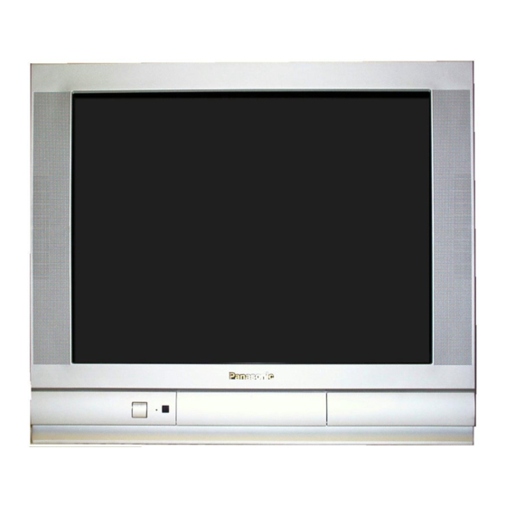
Colour Television
TX-21AS1P
EURO-4 Chassis
AV2 IN
Video (21 pin)
Audio (21 pin)
S-Video IN
(21-pin)
AV2 OUT
Video (21 pin)
Audio (21 pin)
Selectable output (21 pin)
AV3 IN
S-Video IN
(4-pin)
Audio (RCAx2)
Video (RCAx1)
28kV ± 1kV
High Voltage:
Picture Tube:
A51LSK955X05
Audio Output:
2 x 15W (Music Power)
8Ω Impedance
Headphones:
8Ω Impedance
3,5mm
Accessories
supplied :
Remote Control
2 x R6 (UM3) Batteries
Dimensions:
Height:
470mm
Width:
550mm
Depth:
480mm
Net weight:
25kg
Specifications are subject to change without notice.
Weights and dimensions shown are approximate.
NOTE: This Service Manual should be used in conjunction with
the EURO-4 Technical guide.
ORDER No. SM-00044
1V p-p 75Ω
500mV rms 10kΩ
Y: 1V p-p 75Ω
C:0,3V p-p 75Ω
1V p-p 75Ω
500mV rms 1kΩ
Y: 1V p-p 75Ω
C: 0,3V p-p 75Ω
500mV rms 10kΩ
1V p-p 75Ω
51cm
Advertisement
Table of Contents

Related Manuals for Panasonic TX21AS1P


Summary of Contents for Panasonic TX21AS1P
- Page 1 All manuals and user guides at all-guides.com ORDER No. SM-00044 Colour Television TX-21AS1P EURO-4 Chassis SPECIFICATIONS Power Source: 220-240V a.c., 50Hz AV2 IN Video (21 pin) 1V p-p 75Ω Audio (21 pin) 500mV rms 10kΩ Power Consumption: 106W S-Video IN Y: 1V p-p 75Ω...
-
Page 2: Table Of Contents
All manuals and user guides at all-guides.com CONTENTS SAFETY PRECAUTIONS................................2 SERVICE HINTS ..................................3 SERVICE POSITION.................................4 ADJUSTMENT PROCEDURE AND FACTORY SETTINGS .....................5 WAVEFORM PATTERN TABLE ...............................6 ALIGNMENT SETTINGS................................7 BLOCK DIAGRAMS ..................................8 PARTS LOCATION .................................12 REPLACEMENT PARTS LIST ..............................13 SCHEMATIC DIAGRAMS ...............................21 CONDUCTOR VIEWS................................26 SAFETY PRECAUTIONS GENERAL GUIDE LINES... -
Page 3: Service Hints
All manuals and user guides at all-guides.com SERVICE HINTS How to remove the rear cover 1. Remove the 8 screws as shown in Fig.2. SCREWS SCREWS Fig.2. LOCATION OF CONTROLS Y - Board M - Board H - Board Focus Screen E - Board Fig.3. -
Page 4: Service Position
All manuals and user guides at all-guides.com HOW TO MOVE THE CHASSIS INTO SERVICE POSITION Remove 2 screws (A), as shown in Fig.4., and remove speaker assembly. Hold and lift the rear of the chassis and gently pull the chassis toward you, as shown in Fig.5. Release the respective wiring clips and move the EHT lead around to the left side of the CRT neck. -
Page 5: Adjustment Procedure And Factory Settings
All manuals and user guides at all-guides.com ADJUSTMENT PROCEDURE Item / Preparation Adjustments Set the +B voltage up as follows:- +B SET-UP Adjust R811 so that B2 shows 148V±1V. Receive a Greyscale signal. Confirm the following voltages. Set the controls :- ±... -
Page 6: Waveform Pattern Table
All manuals and user guides at all-guides.com WAVEFORM PATTERN TABLE Vert Drive VFLB Vert Out IC451 Pin 3 IC451 Pin 2 IC601 Pin 31 20mS 20mS 20mS H - Out H - Out H - Pulse IC601 Pin 50 IC701 Pin 5 Base Q503 64µS 64µS... -
Page 7: Alignment Settings
All manuals and user guides at all-guides.com ALIGNMENT SETTINGS (The figures below are nominal and used for representative purposes only.) Set the Bass to maximum position, set the Treble to minimum position, press the volume down button (-/v) on the customer controls at the front of the TV and at the same time press the INDEX button on the remote control, this will place the TV into the Service Mode. -
Page 8: Block Diagrams
All manuals and user guides at all-guides.com... - Page 9 All manuals and user guides at all-guides.com...
- Page 10 All manuals and user guides at all-guides.com...
- Page 11 All manuals and user guides at all-guides.com...
-
Page 12: Parts Location
All manuals and user guides at all-guides.com PARTS LOCATION NOTE: The numbers on the exploded view below refer to the mechanical section of the Replacement Parts List. -
Page 13: Replacement Parts List
SPEAKER IC1101 SDA5450C70 MICRO PROCESSOR ENG27507GR TUNER IC1102 27C2001-G18 EPROM * EUR511200 REMOTE CONTROL IC1103 XDG2-02ZP EAROM * TBM4G3008 PANASONIC BADGE IC1104 MN1381-R(TA) RESET TBX4G85700 POWER BUTTON IC1105 MN1381-T(TA) RESET THT1065R CRT FIXING SCREW IC2101 MSP3410DPOC5 AUDIO PROCESSOR TKP4G11471 DOOR LID... - Page 14 All manuals and user guides at all-guides.com Cct Ref Parts Number Description Cct Ref Parts Number Description D702 MTZJT-775.6C DIODE Q551 2SC5517000LB TRANSISTOR D704 MA29TA5 DIODE Q552 2SC1473ATA TRANSISTOR D705 MA4068HTA DIODE Q701 BC857B TRANSISTOR D706 1SS355TE-17 DIODE Q850 2SD2396K-M3 TRANSISTOR D801 RBV4-08...
- Page 15 All manuals and user guides at all-guides.com Cct Ref Parts Number Description Cct Ref Parts Number Description L850 EXCELSA35T COIL JA36 ERJ6GEY0R00 S.M.CARB 0.1W L851 EXCELSA35T COIL JA37 ERJ6GEY0R00 S.M.CARB 0.1W L852 ELEIE470KA COIL JA38 ERJ6GEY0R00 S.M.CARB 0.1W L853 EXCELSA35T COIL JA39 ERJ6GEY0R00...
- Page 16 All manuals and user guides at all-guides.com Cct Ref Parts Number Description Cct Ref Parts Number Description R261 ERJ6GEYJ471 S.M.CARB 0.1W R507 ERG2FJ391H METAL R262 ERJ6GEYJ103 S.M.CARB 0.1W R509 ERDS1TJ152 CARBON 0.5W R263 ERJ6GEYJ473 S.M.CARB 0.1W R510 ERDS1FJ152 CARBON 0.5W R264 ERJ6GEYJ103 S.M.CARB...
- Page 17 All manuals and user guides at all-guides.com Cct Ref Parts Number Description Cct Ref Parts Number Description R855 ERJ6GEYJ752 S.M.CARB 0.1W R1147 ERJ6GEYJ101 S.M.CARB 0.1W R857 ERJ6GEYJ752 S.M.CARB 0.1W R1148 ERJ6GEYJ101 S.M.CARB 0.1W R858 ERJ6GEYJ752 S.M.CARB 0.1W R1149 ERJ6GEYJ223 S.M.CARB 0.1W R859 ERJ6GEYJ753...
- Page 18 All manuals and user guides at all-guides.com Cct Ref Parts Number Description Cct Ref Parts Number Description R3011 ERJ6GEYJ750 S.M.CARB 0.1W R3604 ERJ6GEYJ101 S.M.CARB 0.1W R3012 ERJ6GEYJ750 S.M.CARB 0.1W R3605 ERJ6GEYJ101 S.M.CARB 0.1W R3013 ERJ6GEYJ101 S.M.CARB 0.1W R3606 ERJ6GEYJ101 S.M.CARB 0.1W R3014 ERJ6GEYJ471...
- Page 19 All manuals and user guides at all-guides.com Cct Ref Parts Number Description Cct Ref Parts Number Description 100pF 470pF C562 ECKC2H101J CERAMIC 500V C853 ECKC2H471J CERAMIC 500V 20µF 100µF C563 ECA2EHG220B ELECT 250V C854 ECA1EM102GB ELECT 2.2µF 470pF C564 ECEA2AN2R2SB ELECT 100V C855...
- Page 20 All manuals and user guides at all-guides.com Cct Ref Parts Number Description Cct Ref Parts Number Description 47pF 270pF C2125 ECUV1H470JCX S.M. CAP C3407 ECUV1H271JCX S.M. CAP 70pF 100µF C2126 ECUV1H070DTX S.M. CAP C3408 ECEA1HU101 ELECT 100µF C2127 ECUV1H010CCX S.M. CAP C3601 ECEA1HU101 ELECT...
-
Page 21: Schematic Diagrams
All manuals and user guides at all-guides.com SCHEMATIC DIAGRAMS FOR MODEL TX-21AS1P (EURO-4 CHASSIS) IMPORTANT SAFETY NOTICE Components identified by mark have special characteristics important for safety. When replacing any of these components, use only manufacturers' specified parts. NOTE RESISTOR All resistors are carbon ¼W resistor, unless marked otherwise. - Page 22 All manuals and user guides at all-guides.com...
- Page 23 All manuals and user guides at all-guides.com...
- Page 24 All manuals and user guides at all-guides.com...
- Page 25 All manuals and user guides at all-guides.com...
-
Page 26: Conductor Views
All manuals and user guides at all-guides.com CONDUCTOR VIEW E-BOARD TNP8EE009 TRAN’S DIODES D558 Q3601 L8 D3102 B7 D557 Q3007 M9 D3101 B7 D556 Q3006 N10 D2304 G7 D555 Q3001 N8 D2303 G7 D554 Q2304 I7 D2161 G9 D553 Q2303 M6 D2105 G10 D552 Q2302 I7... - Page 27 All manuals and user guides at all-guides.com Y - BOARD TNP8EY013 DIODES D354 D355 D356 D357 D358 D359 D360 D361 D362 D363 D364 TEST POINTS TPY1 E4 TPY2 F5 TPY3 F4 TPY4 E3 TPY5 D3 TPY6 B6 TRANSISTORS Q351 Q352 Q353 Q354 I.C.’S...
- Page 28 All manuals and user guides at all-guides.com M - BOARD TNP8EM024 TRANSISTORS Q1061 Q1062 Q1900 Q1901 Q3201 Q3202 Q3203 Q3204 Q3205 Q3206 Q3207 Q3208 Q3209 DIODES D1055 D1061 D1900 D3201 D3202 D3203 IC’S IC1061 IC1900 IC1901...
- Page 29 All manuals and user guides at all-guides.com H - BOARD TNP8EH002 TRANSISTORS Q3401 Q3402 I.C.’S IC3401 C2...
- Page 30 All manuals and user guides at all-guides.com NOTES...
- Page 31 All manuals and user guides at all-guides.com NOTES...
- Page 32 All manuals and user guides at all-guides.com...
- Page 33 All manuals and user guides at all-guides.com...
- Page 34 All manuals and user guides at all-guides.com...
Need help?
Do you have a question about the TX21AS1P and is the answer not in the manual?
Questions and answers