Table of Contents
Advertisement
Quick Links
Advertisement
Table of Contents

Summary of Contents for EELP PSL Series
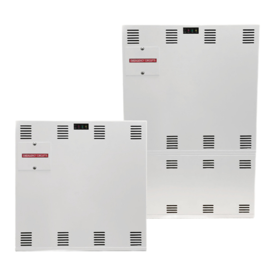
- Page 1 Installation And Operation Instructions For PSL Series Inverter Power Systems Models: PSL-375 and PSL-600 True Sinusoidal Output Power PSL-375 Model PSL-600 Model EELP, Inc. One Neshaminy Interplex Dr. Suite 300 - Trevose, PA 19053 (800) 490-4496 www.elep.net...
- Page 2 READ AND FOLLOW ALL SAFETY INSTRUCTIONS IMPORTANT SAFEGUARDS When using electrical equipment, basic safety precautions should always be followed, includ- ing the following: READ AND FOLLOW ALL SAFETY INSTRUCTIONS: • Do not use outdoors. • Do not let power supply cords touch hot surfaces. •...
-
Page 3: Table Of Contents
Table of Contents Description Page Section 100 System Installation Instructions 101. Specifications ....................... 4 102. Receiving, Moving and Storing Systems and Batteries ........5 102.1 Shipping Damage ....................5 102.2 Temporary Storage of Units and Batteries ............5 103. Installation Requirements ..................5 103.1 Operating Environment .................. -
Page 4: Section 100
Section 100 System Installation Instructions 101. ������� Input • Input voltage: Universal 120 or 277Vac. • Input frequency: 60HZ ±2% • Input surge protection: Meets UL 924 Output • Output voltage: Universal 120 or 277Vac, 60HZ. Other voltages available upon request •... -
Page 5: 102. Receiving, Moving And Storing Systems And Batteries
102. Receiving, Moving and Storing Systems and Batteries 102.1 Shipping Damage Inverter system batteries are shipped separately. Carefully inspect all cartons upon receipt for evidence of shipping damage. Notify carrier immediately of leaking or damaged cartons for possible concealed damage. 102.2 Temporary Storage of Units and Batteries For temporary storage of PSL inverter systems and batteries prior to installation, select a clean, cool, dry location with normal ventilation for human habitation and level floors. -
Page 6: 104.2 Mounting Hardware
104.2 Mounting Hardware Mounting hardware is not provided. Care should be taken when selecting mounting hardware to as- sure that it is the proper type for the application and sized to safely support the systems full weight when installed assuring safe and secure attachment of system to wall surface or building structures. For ease of installation, the factory recommends that the head size of mounting screws or bolts be small enough to pass through the keyhole knockouts provided for mounting. -
Page 7: 105.1 Ac Wiring Preparations
105.1 AC Wiring Preparations 1. Remove the system’s front cover. 2. Make sure the PSL inverter system input and output voltages are correct for the particular appli- cation. Remember that the PSL system provides single-phase power only. 3. The input circuit breaker in the input service panel provides the means for disconnecting AC to the PSL inverter system. - Page 8 Switched Load Operation - Single Circuit - Connected fixure(s) can be extremely switched and will illuminate upon loss of utility AC power regardless of external switch position. See Wiring Diagram 4. NORMALLY ON LOADS NORMALLY OFF LOADS NORMALLY OFF NORMALLY ON OUTPUT OUTPUT AC INPUT...
-
Page 9: 106. Battery Information
106. Battery Information Important Safety Precautions The installer must take these precautions: 1) Wear protective clothing, eye-wear, rubber gloves and boots. Batteries contain corrosive acids or caustic alkalis and toxic materials and can rupture or leak if mistreated. Remove rings and metal wristwatches or other metal objects and jewelry. -
Page 10: 106.2 Battery Installation And Connection
106.2 Battery Installation and Connection Battery Placement: The PSL-375 models are provided with (5) 12V Lead Calcium batteries (60Vdc string). The PSL-600 Models are provided with (8) 12V Lead Calcium batteries (96 Vdc string). PSL-375: Carefully place all batteries in the unit battery (lower) compartment with positive (+) red terminals facing outwards and upwards. - Page 11 60VDC BATTERY WIRING DIAGRAM 1 BUSHING FRONT VIEW BLACK BATTERY COMPARTMENT WHITE WHITE WHITE WHITE BATTERY WIRING DIAGRAM 2 96 VDC BUSHING FRONT VIEW BLACK UPPER WHITE WHITE WHITE BATTERY COMPARTMENT WHITE BUSHING LOWER BATTERY WHITE WHITE WHITE COMPARTMENT...
-
Page 12: 106.3 Battery Voltage Check
106.3 Battery Voltage Check Using a digital volt-ohm meter, check for correct nominal battery voltage between DC Input NEG and POS wires. Voltage reading should be ±10% of system’s nominal 60Vdc for PSL-375, 96Vdc for PSL-600 operating voltage. 107. Final Installation Checklist IMPORTANT: Before proceeding to the System Start-Up Procedure (Section 108) complete the Final Installation Checklist below. -
Page 13: 110. System Self Test / Diagnostics
110. System Self-Tests Once the system is properly installed in accordance with the installation instructions, and AC power is supplied to the, the dual color (SDT STATUS) LED indicator will illuminate, followed by the amber (INV ON) LED indicator. The dual color LED indicates the unit's status. A steady GREEN LED indicates normal service; A blinking GREEN/RED LED indicates the battery is charging;... -
Page 14: 200.1 Safe Shut Down Procedure
200. Maintenance 200.1 Safe Shut Down Procedure CAUTION: To avoid possible equipment damage or personal injury, assume that there is AC voltage present inside the PSL inverter system unit any time AC input power or DC battery voltage is applied. The inverter is capable of providing output voltage from the batteries even when there is no AC input line voltage. -
Page 15: 200.4 Routine Battery Inspection And Maintenance
200.4 Routine Battery Inspection and Maintenance Sealed Lead-Calcium Batteries Maintenance-free cells are the most common type of battery used today in standby equipment. By design it is as maintenance free as a battery can be. It is recommended, however, that some simple steps be taken to increase system life and maximize reliability: A) A quarterly visual check of the battery should be conducted to look for deformities in the battery case, electrolyte leakage and/or terminal corrosion.
Need help?
Do you have a question about the PSL Series and is the answer not in the manual?
Questions and answers