Table of Contents
Advertisement
Quick Links
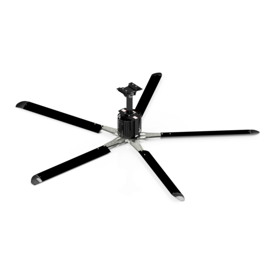
Direct Drive HVLS Fan
User's Manual
E506041
This manual applies to fans manufactured
beginning January 2024 with the serial number
F61709236 or greater.
Do not install, operate, or service this product
User's Manual
unless you have read and understand the
Safety Practices, Warnings, and Installation and
Installation, Operations
Operating Instructions contained in this manual.
Failure to do so could result in death or serious
Maintenance and Parts
injury.
Part No. 6022221C
Part of ASSA ABLOY
© ASSA ABLOY 2024
Advertisement
Table of Contents

Summary of Contents for Assa Abloy F61709236
- Page 1 User's Manual E506041 This manual applies to fans manufactured beginning January 2024 with the serial number F61709236 or greater. Do not install, operate, or service this product User’s Manual unless you have read and understand the Safety Practices, Warnings, and Installation and Installation, Operations Operating Instructions contained in this manual.
-
Page 2: Limited Product Warranty
Limited Product Warranty LIMITED PRODUCT WARRANTY Warranty information for the Direct Drive HVLS Fan can be found by scanning the QR codes or clicking the links below. Click here to view the 4Front U.S. Click here to view the and Canada Warranty. International Warranty. -
Page 3: Table Of Contents
Table of Contents TABLE OF CONTENTS LIMITED PRODUCT WARRANTY ....................3 INTRODUCTION ..........................7 USER MANUAL ........................7 HOW TO USE HOW TO USE THIS MANUAL ................ 7 SAFETY SIGNAL WORDS....................... 8 OPERATIONAL SAFETY ......................9 OWNER’S RESPONSIBILITIES .................... 12 NATIONAL FIRE PROTECTION ASSOCIATION STANDARD .......... - Page 4 Table of Contents VERIFY CLEARANCE AND CABLE TENSION ..............31 INSTALL THE REMOTE CONTROL ..................32 ELECTRICAL SCHEMATICS ...................... 33 1PH WIRING DETAILS ......................33 VARIABLE FREQUENCY DRIVE I/O ..................36 MULTI-FAN WIRING DETAILS — OPTIONAL ..............37 IFAN WIRING DETAILS ......................38 TEMPERATURE/HUMIDITY CONTROL WIRING DETAILS —...
- Page 5 Table of Contents DIAGNOSTIC SCREEN......................52 BUTTON INFORMATION ....................... 53 FAULT CODE .......................... 53 FAULT CODE DEFINITIONS ....................54 PASSCODE PROTECTION ....................55 MULTI-FAN CONTROL — OPTIONAL ................. 56 TEMPERATURE CONTROL — OPTIONAL ................. 56 PLANNED MAINTENANCE ......................58 ANNUAL MAINTENANCE ..................... 58 TROUBLESHOOTING GUIDE ....................
-
Page 6: Introduction
Introduction INTRODUCTION Welcome and thank you for choosing this Direct Drive fan from 4Front Engineered Solutions, Inc. USER MANUAL This User’s Manual contains information you need to safely install, operate, and maintain the fan. It also contains a complete parts list and information about ordering replacement parts. Please keep and read this User’s Manual before using your new fan. -
Page 7: Safety Signal Words
Introduction SAFETY SIGNAL WORDS You may find safety signal words such as DANGER, WARNING, CAUTION, or NOTICE in the User’s Manual. The use of Safety Signal Words is explained below. WARNING AND CAUTION SYMBOL This symbol is the Safety alert symbol. It is used to alert you to potential personal injury hazards, Obey all safety messages that follow this symbol to avoid possible death or injury.. -
Page 8: Operational Safety
Introduction NOTICE SYMBOL Notice is used to address practices not related to personal injury. OPERATIONAL SAFETY READ THESE SAFETY PRACTICES BEFORE INSTALLING, OPERATING, OR SERVICING THE FAN. READ AND FOLLOW THE OPERATING INSTRUCTIONS IN THIS MANUAL BEFORE OPERATING THE FAN. If you do not understand the instructions, ask your supervisor for instruction. - Page 9 Introduction Installation of the equipment must comply with local and national electrical codes and must be in accordance with ANSI/NFPA 7-1999. Do not use this fan until you have received proper training. Improper use could result in property damage, bodily injury and/or death. Read and follow Operating Instructions on page <?>...
- Page 10 Introduction To reduce the risk of injury to persons, install fan so that the blades are at least 3.05m (10’) above the floor. Installation work and electrical wiring must be done by qualified person(s) in accordance with all applicable codes and standards. When cutting or drilling into wall or ceiling, do not damage electrical wiring and other hidden utilities.
-
Page 11: Owner's Responsibilities
Introduction Stay alert, watch what you are doing, and use common sense when installing fans. Do not install fans when tired, or under the influence of drugs, alcohol, or medications. A moment of inattention while installing fans may result in serious personal injury. The installation of this fan requires the use of some power tools. -
Page 12: National Fire Protection Association Standard
Introduction NATIONAL FIRE PROTECTION ASSOCIATION STANDARD In accordance with NFPA 13 Standard from the National Fire Prevention Association as referenced in sections 12.1.4 and 11.1.7: High Volume Low Speed (HVLS) Fans: The installation of HVLS fans in buildings equipped with sprinklers, including ESFR sprinklers, shall comply with the following: The maximum fan diameter shall be 24 feet (7.3m). -
Page 13: Hardware
Hardware HARDWARE Mount ─ Building Guy wire assembly (x4) 1/2-13UNC x 2-1/2 (x4) 1/2-13UNC lock nut Mount ─ Assembly (x2) 1/2-13UNC x 4-1/2 bolt Safety cable (x4) 1/2 dia. washer (x2) 1/2-13UNC nyloc lock nut Mount ─ Motor frame (x4) 1/2-13UNC x 1-1/4 bolt Identification labels (x4) 1/2-13UNC lock nut Fan diameter... -
Page 14: Fan Kit
Fan Kit FAN KIT PACKING KIT (STANDARD) 1. Blade Box - Five (5) blades 2. Fan Motor Box a. Motor assembly with covers. b. Remote control panel with junction box (optional) c. Category 5e cable - 100 ft (blue) (optional) d. -
Page 15: For Optional Network (Ifan Or Multi-Fan Fans Only)
Fan Kit FOR OPTIONAL NETWORK (IFAN OR MULTI-FAN FANS ONLY) Ensure the Fan Network Address number matches the network layout drawing where applicable. Consult the square Network Address label on the front of the VFD enclosure. January 2024 6022221C - Direct Drive HVLS Fan UM... -
Page 16: Installation Considerations
Installation Considerations INSTALLATION CONSIDERATIONS Figure 1 ROOF SLOPE The chart below does not account for any possible obstructions below the mounting positions. All fans must still maintain 3’ between blades and typical obstructions. DIRECT DRIVE FAN Roof Slope* 2/12 3/12 4/12 Hanging Maximum... -
Page 17: Roof Angles
Installation Considerations Failure to maintain exclusion zones outlined in this section could result in fan failures, including blade separation, which could result in death or serious injury. DO NOT operate fans when physical obstructions or HVAC air flows extend into exclusion zones. Regularly inspect fans to ensure exclusion zones remain clear of interference before operating the fan. -
Page 18: Clearance From Hvac Equipment
Installation Considerations CLEARANCE FROM HVAC EQUIPMENT For applications near HVAC equipment, such as diffusers, radiant heaters, exhaust fans, louvers, etc., the HVLS fan must be installed at minimum distances. Refer to the figures below. Fans located above HVAC equipment must have a minimum clearance of greater than or equal to 1 fan diameter. See Figure Figure 2 Greater than... - Page 19 Installation Considerations Fans located at or below HVAC equipment musts have a minimum clearance of greater than or equal to 2 fan diameters. See Figure Figure 3 Greater than 2 fan dia. January 2024 6022221C - Direct Drive HVLS Fan UM...
-
Page 20: Clearance From Solid Obstructions
Installation Considerations CLEARANCE FROM SOLID OBSTRUCTIONS For applications near solid obstructions, the HVLS fan must be installed at minimum distances. Fans located near solid obstructions, such as walls racks or columns greater than 1FT wide, should have a minimum distance of one half (1/2) fan diameter from the end of the blade. Fans located above solid obstructions, such as racks, walls, etc. -
Page 21: Building Structure
Installation Considerations BUILDING STRUCTURE Figure 5 Grade 5 hardware or better For open structure roof designs, the fan should only be hung from either an I-Beam or angle 1/2-13UNC x 4-1/2 (x4) iron. Do not hang from purlins, posts, or a truss structure unless all of the following apply: The truss can handle the load of the fan The bottom chords of the truss are larger that... - Page 22 Installation Considerations If the fan is part of a networked system, ensure placement is in accordance with the building layout. The fan network is located on the front panel of the VFD box Be sure to comply with all local and national codes during installation.
-
Page 23: Installation
Installation Figure 6 INSTALLATION 1/2-13UNC x 2-1/2 bolts (x4) Before installation, make certain that the 1/2-13UNC power is disconnected and properly locked lock nut (x4) out. Pivot bolt For fans that will be subjected to high cross Shim (x2) (as req’d) winds due to open bay doors or air conditioning Angle Pivot bolt... - Page 24 Installation 6. Fasten the clamps using the supplied 1/2” Figure 8 dia. X 21/2” screws, lock nuts, and washers. Laminated wood beam 7. Torque to 44-48 ft-lbs. See Figure 7. Laminated wood beam bracket LAMINATED WOOD BEAM MOUNTING (OPTIONAL KIT 6018028) 1.
-
Page 25: Install The Powerhead (Motor Assembly)
Installation INSTALL THE POWERHEAD (MOTOR Figure 10 ASSEMBLY) The power head may be oriented as required for aesthetics or commonality. Leave the protective bumper on the bottom of the power head assembly until the power head is mounted in place. 1. -
Page 26: Install The Vfd Box
Installation Figure 12 INSTALL THE VFD BOX Cable clamps Space cable Verify the voltage and phase before mounting the clamps 6" apart box. Ensure the voltage from the building source wiring matches the voltage listed on the VFD box. Safety cable The VFD box must be installed outside and Motor frame a safe distance from the blade diameter for... -
Page 27: Install Guy Wires
Installation INSTALL GUY WIRES Figure 14 Guy wires are designed to constrain lateral movement of the fan when it is operating. This movement may be due to impacts on the fan or winds impinging on the blades causing the fan to sway. -
Page 28: Install Motor Cover
Installation Figure 15 a. Slide two of the supplied 1/8” dia. cable clamps over one end of the wire. b. Feed that end through the building structure and back through the clamp fasteners. c. Securely tighten the clamp fasteners so that they cannot slip. -
Page 29: Install Blades
Installation INSTALL BLADES To reduce the risk of personal injury, do not bend the blade brackets when installing the Installing the Blades brackets or cleaning the fan. Click here to view the video. Do not insert foreign objects in between rotating fan blades. -
Page 30: Verify Clearance And Cable Tension
Installation Figure 19 Do not lean on the blade. Damage to the strut may occur. 7. Install the retention lock nuts. Blade retention 8. Hand tighten the nuts to ensure the strut lock nuts arms are firmly pressing against the hub. 9. -
Page 31: Install The Remote Control
Installation INSTALL THE REMOTE CONTROL Do not over-torque the mounting screws. Damage to the display screen may occur if Install Remote Control you over-torque the mounting screws. Click here to view the video. It is your responsibility to torque the screws Figure 21 properly. -
Page 32: Electrical Schematics
Electrical Schematics ELECTRICAL SCHEMATICS Before doing any electrical work, make certain the power is disconnected and properly locked out and tagged out. Failure to do so may result in death or serious injury. All electrical troubleshooting and repair must be done by a qualified technician and meet all applicable codes. - Page 33 Electrical Schematics SIZING CHART 6022500 6022501 6022520 6022504 6022505 6022542 6022508 6022509 6022454 6022512 6022513 6022517 VOLTAGE 120V/1PH/50 60HZ 230V/1PH/50 60HZ 230V/1PH/50 60HZ 19.3A 12.6A 13.0A FUSE KTKR20 KTKR15 KTKR10 0.8kW, 6 FLA@ 0.8kW, 6 FLA@ 1.2kW, 5.6 FLA@ MOTOR 230V/60HZ 230V/60Hz 230V/60HZ...
- Page 34 Electrical Schematics SIZING CHART 6022502 6022503 6022540 6022541 6022506 6022507 6022543 6022544 6022510 6022511 6022546 6022547 6022514 6022515 6022518 6022519 VOLTAGE 230/3PH/50 60HZ 460V/3PH/50 60HZ 230V/3PH/50 60HZ 460V/3PH/50 60HZ 7.3A 3.8A 7.5A 3.4A FUSE KTKR10 KTKR5 KTKR10 KTKR5 0.8kW, 6.0 A@FLA 0.8kW, 6.0 FLA@ 1.2kW, 5.6AFLA @ 1.2KW, 2.8 FLA@...
-
Page 35: Variable Frequency Drive I/O
Electrical Schematics VARIABLE FREQUENCY DRIVE I/O Figure 24 January 2024 6022221C - Direct Drive HVLS Fan UM... -
Page 36: Multi-Fan Wiring Details - Optional
Electrical Schematics MULTI-FAN WIRING DETAILS — OPTIONAL Figure 25 TYPICAL MULTI FAN BELDEN 8723 OR EQUIV. DAISY CHAIN VFD ENCLOSURE COMMUNICATION CABLE (SUPPLIED BY OTHERS) (CONDUIT BY OTHERS) NETWORK FIRE CONTROL PANEL (6020547) LOCATE AS CLOSE TO BUILDING FIRE ENCLOSURE AS POSSIBLE SUPPLY VOLTAGE 115VAC (SUPPLIED BY ENTREMATIC AS AN OPTION... -
Page 37: Ifan Wiring Details
Electrical Schematics IFAN WIRING DETAILS Figure 26 BELDEN 8723 OR EQUIV. COMMUNICATION CABLE (SUPPLIED BY OTHERS) (CONDUIT BY OTHERS) NETWORK FIRE CONTROL PANEL (6020547) LOCATE AS CLOSE TO BUILDING BATTERY FIRE ALARM AS POSSIBLE POWER INSERT AS SHOWN SUPPLY VOLTAGE 115VAC 24VDC RESET (SUPPLIED BY ENTREMATIC AS AN... -
Page 38: Temperature/Humidity Control Wiring Details - Optional
Electrical Schematics TEMPERATURE/HUMIDITY CONTROL WIRING DETAILS — OPTIONAL Figure 27 TOUCH MODBUS TEMP & HUM HVLS SCREEN SENSOR/CONTROLLER CONTROLLER MODBUS ADDRESS 100 ENCLOSURE GREEN BLACK DATA - DATA+ FIRE ALARM GREEN JUMPER F.G. TEMP BLACK 6022221C - Direct Drive HVLS Fan UM January 2024... -
Page 39: Fire Control System Fan Shutdown - Optional
Electrical Schematics FIRE CONTROL SYSTEM FAN SHUTDOWN Figure 28 — OPTIONAL (mounted in enclosure) This fan includes a fire alarm option. This option allows the fan to be shut down by the fire control system in case of an emergency. Ensure the fire alarm jumper is in place or the building fire control system is connected and the jumper removed. - Page 40 Electrical Schematics TEST THE FIRE CONTROL SHUTDOWN SYSTEM To test the fire control system fan shutdown operation: 1. Remove the wire from the NC contact at the Figure building fire control panel. See The fan should coast to a stop. To enable the fire control system fan shutdown option,: If you leave the jumper is left installed, the fan will not shut down due to fire control system...
-
Page 41: Fire Control System Fan Shutdown - Standard Installation (6015291)
Electrical Schematics FIRE CONTROL SYSTEM FAN SHUTDOWN — STANDARD INSTALLATION (6015291) Figure 29 January 2024 6022221C - Direct Drive HVLS Fan UM... -
Page 42: Fire Control System Fan Shutdown - Network Installation (6020547)
Electrical Schematics FIRE CONTROL SYSTEM FAN SHUTDOWN — NETWORK INSTALLATION (6020547) Figure 30 120V/60HZ POWER SUPPLY PRIMARY FUSING AND DISCONNECT BY OTHERS SLOT 0 BCPD 15A (CB/FU) DV102 PANEL FLA 0.3 DELTA FU101 SCCR 5KA COMPACT 1011 1013 PLC101 1021 1023 JUMPER FIRE ALARM... -
Page 43: 550-600V Supply Wiring Details - Optional
Electrical Schematics 550-600V SUPPLY WIRING DETAILS — OPTIONAL To connect a 480V fan to a 550-600V building supply, you must install a step down transformer assembly (6017277) between the power supply and the VFD enclosure. Wiring (by others) must be 600V rated 14 awg. -
Page 44: Hmi Setup
HMI Setup HMI SETUP Figure 33 The Human Machine Interface (HMI) program controls up to a total of six fans. The program also allows the use of two types of accessories: Temperature Control High Wind Shutdown (anemometer) Both accessories can be used with a single fan configuration. -
Page 45: Enable The Temperature Control Option (Optional)
HMI Setup ENABLE THE TEMPERATURE CONTROL Figure 32 OPTION (OPTIONAL) The Temperature Control options require the use of an optional temperature sensor (Std: 6013861 or 4X: 6016700). The 4X option should only be used if the temp sensor part number 6016700 is being used. If you chose a single fan for the Fan Quantity on the first screen, the Enable Temperature Control screen displays. -
Page 46: Set The Unit Of Wind Speed
HMI Setup 1. Press YES to enable the wind shutdown option; otherwise press NO. Figure 35 The option you selected changes to green. Figure SET THE UNIT OF WIND SPEED The maximum speed and duration is set at the factory. If you want to change these properties, you must contact the factory. -
Page 47: Post Configuration Tasks
HMI Setup POST CONFIGURATION TASKS After you configure the HMI program for your location, you should: 1. Operate the fan using the Operating Instructions on page 2. Check the fan for proper rotation direction, stability, and noise level. 3. Train authorized personnel how to use the fan using the Operating Instructions on page TEMPERATURE CONTROL INSTALLATION... - Page 48 HMI Setup 2. Mount the wind speed/direction sensor to the pipe. You can pass the data cable through the center of the mounting pipe or the outside of the mounting pipe. 3. Route the data cable and terminate it at the VFD box.
-
Page 49: Operating Instructions
Operating Instructions OPERATING INSTRUCTIONS FAN CONTROL SCREEN Figure 36 RPM increase Start/Stop Forward Reverse RPM decrease Current fan (multi fan only) Previous fan Next fan (multi fan only) (multi fan only) Active alarm (see fault code screen) Menu Comm status Fan speed January 2024 6022221C - Direct Drive HVLS Fan UM... -
Page 50: Verify Prior To Operation
Operating Instructions Figure 37 Before operating the industrial fan, read and follow the Safety Practices, Warnings and Operating Instructions in this manual. Use by untrained personnel could result in death or serious injury. VERIFY PRIOR TO OPERATION Before operating the fan, verify the following: The voltage and phase are correct The clearance from obstructions matches the requirements... -
Page 51: Change The Fan Direction
Operating Instructions Figure 38 2. Press the Start button, and then select the beginning fan rotation direction. See Figure 3. Set the desired speed by pressing either RPM increase or RPM decrease until your desired speed displays. Maximum speed is 10. Minimum speed is 1. -
Page 52: Button Information
Operating Instructions Figure 39 BUTTON INFORMATION To navigate back to the previous screen, press the green return arrow. The Wind button displays the Wind Control screen. The Fault Code button displays the Active Alarm screen. The Temp button displays the Current Temperature screen. -
Page 53: Fault Code Definitions
Operating Instructions FAULT CODE DEFINITIONS CODE DESCRIPTION No Alarm/Fan OK Overcurrent during acceleration Overcurrent at speed Overcurrent during deceleration/stop Overvoltage during acceleration Overvoltage at speed Overvoltage during deceleration/stop Inverter overload Motor overload Input phase loss Stall prevention Brake transistor alarm Ground fault overcurrent at start Output phase loss External thermal relay operation... -
Page 54: Passcode Protection
Operating Instructions PASSCODE PROTECTION Figure 40 You can assign a passcode to the remote to prevent unauthorized use. 1. Press the Menu button on the main screen. 2. Press the Passcode button on the Diagnostic screen. 3. Type your passcode. The default passcode is 1111. -
Page 55: Multi-Fan Control - Optional
Operating Instructions MULTI-FAN CONTROL — OPTIONAL Figure 42 Press the Previous or Next fan buttons until you reach the fan you want to control. See Figure The All option lets you control all of the fans at the same time. TEMPERATURE CONTROL —... - Page 56 Operating Instructions The fan decreases in speed as the Figure 44 temperature decreases until the temperature falls below the start point. When the temperature falls below the start point minus the increment value, the fan automatically shuts off. The fan stops on its own.
-
Page 57: Planned Maintenance
Planned Maintenance PLANNED MAINTENANCE Before service, inspection, or cleaning make certain that the power is disconnected and properly locked out. Before servicing the fan, read Operational Safety on page 8 Operating Instructions on page 49. Failure to do so could result in death or serious injury. To ensure the continued proper operation of your fan, perform the following planned maintenance procedures. - Page 58 Planned Maintenance a. Re-tighten as required. 7. Clean fan blades as required. a. Use a soft dry cloth. b. If necessary, use a mild detergent to clean surfaces. Figure 45 Legend Symbol Description Cleaning (Frequency - Quarterly) Visually Inspect (Replace Damaged Or Worn) Blow with Compressed Air (Frequency - Annually) 6022221C - Direct Drive HVLS Fan UM...
-
Page 59: Troubleshooting Guide
Troubleshooting Guide TROUBLESHOOTING GUIDE Before servicing the industrial fan, read and follow Operational Safety on page 8 Operating Instructions on page 49. Failure to do so could result in death or serious injury. Before doing any electrical work, make certain the power is disconnected and properly locked or tagged off. - Page 60 Troubleshooting Guide PROBLEM POSSIBLE CAUSE SOLUTION The fan does not operate. No power to the control panel. Ensure the disconnect is in the ON position Check for primary power at the terminals. Primary fuse(s) are blown. Replace fuse(s). Fan does not operate, but the There is an obstruction Check the fan unit.
-
Page 61: Variable Frequency Drive Fault Codes
Variable Frequency Drive Fault Codes VARIABLE FREQUENCY DRIVE FAULT CODES The Variable Frequency Drive (VFD) are shown on the VFD display. Figure 46 Operation Panel Operation Panel Name Name Indication Indication Inverter overload trip E--- Faults history E.THT (electronic thermal O/L HOLD Operation panel lock relay function) -
Page 62: Components And Specifications
Components and Specifications COMPONENTS AND SPECIFICATIONS VFD BOX NEMA 1 Solid State VFD (Variable Frequency Drive) 120VAC, 1PH before the 208-240VAC 208-240VAC 1PH, 208 – 480 VAC 3PH Line reactor (where required) Class CC fuses UL and UL-C listed panel and components Power disconnect MOTOR IP65 DC Brushless Direct Drive Motor... - Page 63 Components and Specifications Figure 47 VFD box Universal mount VFD unit Clamp Safety cable Guy wires Powerhead Motor cover Winglet Blade January 2024 6022221C - Direct Drive HVLS Fan UM...
-
Page 64: Parts List
Parts List PARTS LIST To ensure proper function, durability and safety of the product, only replacement parts that do not interfere with the safe, normal operation of the product must be used. Incorporation of replacement parts or modifications that weaken the structural integrity of the product, or in any way alter the product from its normal working condition at the time of purchase from 4Front could result in product malfunction, breakdown, premature wear, death or serious injury. -
Page 65: Fan
Parts List Figure 48 Laminated wood beam shown for clarification January 2024 6022221C - Direct Drive HVLS Fan UM... - Page 66 Parts List For corrosion resistant fans, consult factory for parts. ITEM QUANTITY DESCRIPTION PART NUMBER DD Powerhead, 8/10/12/14 Low 6021600 DD Powerhead, 16/18/20/24 Low 6021602 DD Powerhead, 8/10/12/14 High 6021601 DD Powerhead, 6/18/20/24 High 6021603 Silver Motor Cover 6023264 Black Motor Cover 6023019 Safety Cable - 170"...
- Page 67 Parts List ITEM QUANTITY DESCRIPTION PART NUMBER Plate Hanger Bracket Clamp 6014953 Plate, Clamp Spacer 6014954 Guy Wire Kit - 6FT, 7FT, 8FT (includes items 16 & 17) 6014914 Guy Wire Kit - 9FT, 10FT EXT (includes items 16 & 17) 6015678 Secondary Strap Tie, Ball Lock 6015265...
-
Page 68: Vfd Box
Parts List VFD BOX Figure 49 VFD PANEL 120V/1P VFD PANEL, 120V/1P, 8FT 6022500 VFD PANEL, 120V/1P, 10FT 6022504 VFD PANEL, 120V/1P, 12FT 6022508 VFD PANEL, 120V/1P, 14FT 6022512 ITEM QUANTITY DESCRIPTION PART NUMBER Interface, HVLS, DIN Mount 6015547 Mitsubishi VFD, DD, 120V/1P 6022070 Fuse 20A, 60V, KTKR20 6011801... - Page 69 Parts List VFD PANEL 230V/1PH VFD PANEL, 230V/1P, 8FT 6022501 VFD PANEL, 230V/1P, 10FT 6022505 VFD PANEL, 230V/1P, 12FT 6022509 VFD PANEL, 230V/1P, 14FT 6022513 VFD PANEL, 230V/1P, 16FT 6022517 VFD PANEL, 230V/1P, 18FT 6022520 VFD PANEL, 230V/1P, 20FT 6022542 VFD PANEL, 230V/1P, 24FT 6022545 ITEM...
- Page 70 Parts List VFD PANEL 480V/3P VFD PANEL, 480V/3P, 8FT 6022503 VFD PANEL, 480V/3P, 10FT 6022507 VFD PANEL, 480V/3P, 12FT 6022511 VFD PANEL, 480V/3P, 14FT 6022515 VFD PANEL, 480V/3P, 16FT 6022519 VFD PANEL, 480V/3P, 18FT 6022541 VFD PANEL, 480V/3P, 20FT 6022544 VFD PANEL, 480V/3P, 24FT 6022547 ITEM...
-
Page 71: Remote Control Panel
Parts List REMOTE CONTROL PANEL Figure 50 WHT/BRN WHT/GRN ITEM QUANTITY DESCRIPTION PART NUMBER Touch screen Controller, Kelley 6015758 Touch screen Controller, Serco 6015759 Touch screen Controller, Epic 6023293 J-Box, Plastic, Ivory 6015648 Cable Cat5, 100’ w/Ferrule (Blue) 6015651 January 2024 6022221C - Direct Drive HVLS Fan UM... -
Page 72: Temperature Control - Optional
Parts List TEMPERATURE CONTROL — OPTIONAL Figure 51 ITEM QUANTITY DESCRIPTION PART NUMBER Temp Control Assembly 6022769 6022221C - Direct Drive HVLS Fan UM January 2024... - Page 73 Notes NOTES January 2024 6022221C - Direct Drive HVLS Fan UM...
- Page 74 1612 Hutton Drive, Suite 140 Carrollton, TX 75006 Tel: (972) 466-0707 Fax: (972) 323-2661 APS Resource 262.518.1000 Scan this code or click For replacement parts, here to locate an APS please call the number Resource distributor. above. © ASSA ABLOY...
Need help?
Do you have a question about the F61709236 and is the answer not in the manual?
Questions and answers