Table of Contents
Advertisement
Quick Links
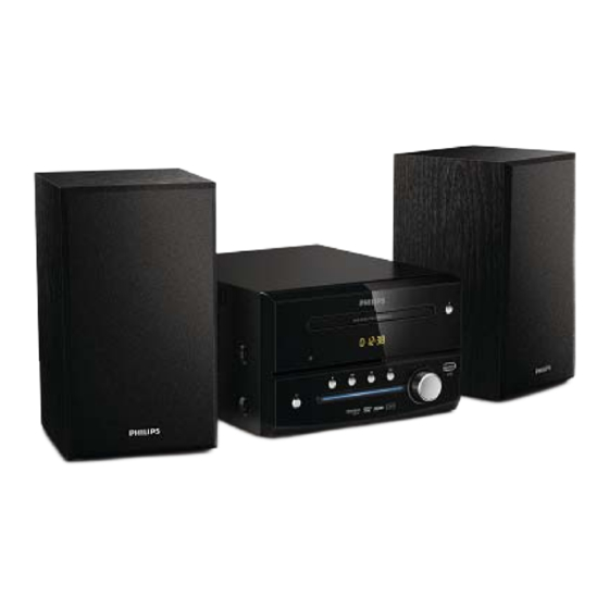
DVD Micro Theater
Service Manual
·How to remove the CD manually from the tray.....................................................................................2
·How to check the return Unit............................................................. ..................................................3-6
·Software Upgrade...................................................................................................................................7
·How to select right language.......................................................................................................8
·Block diagram.......................................................................................................................9-1
·Wiring diagram.......................................................................................................................9-2
·Main board
Circuit diagram....................................................................................................9-3....9-8
Layout diagram......................................................................................................9-9....9-10
·Exploded diagram...............................................................................................................9-11
·Revision List............................................................................................................................................10
Service Manual
©Copyright 2012 Philips Consumer Electronics B.V. Eindhoven, The Netherlands
All rights reserved. No part of this publication may be reproduced, stored in aretrieval system or
transmitted, in any form or by any means, electronic, mechanical, photocopying, or otherwise
without the prior permission of Philips.
Published by by MTC-FK 1209 AV System
TABLE OF CONTENTS
Printed in The Netherlands Subject to modification
1
MCD130/93 MCD130/96
PHILIPS
MCD130
Page
3141 785 34620
Version 1.0
Advertisement
Table of Contents

Related Manuals for Philips MCD130/93


Summary of Contents for Philips MCD130/93
-
Page 1: Table Of Contents
·Revision List……...………………………..……….....................10 Service Manual ©Copyright 2012 Philips Consumer Electronics B.V. Eindhoven, The Netherlands All rights reserved. No part of this publication may be reproduced, stored in aretrieval system or transmitted, in any form or by any means, electronic, mechanical, photocopying, or otherwise without the prior permission of Philips. - Page 2 2.0 SAFTETY INSTRUCTIONS WAARSCHUWING WARNING Alle IC’s en vele andere halfgeleiders zijn All ICs and many other semi-conductors are gevoelig voor electrostatische ontladingen susceptible to electrostatic discharges (ESD). (ESD). Careless handling during repair can reduce life Onzorgvuldig behandelen tijdens reparatie kan drastically.
- Page 3 2.1 ESD PROTECTION When the power supply is being turned on, you may not remove this laser cautions label. If it removes, radiation of laser may be received. PREPARATION OF SERVICING Pickup Head consists of a laser diode that is very susceptible to external static electrocity. Although it operates properly after replacement, if it was subject to electrostatic discharge during replacement, its life might be shortened.
- Page 4 SAFTY NOTICE SAFTY PRECAUTIONS LEAKAGE CURRENT CHECK Plug the AC line cord directly into a 120V AC outlet (do Measure the AC voltage across the 1500 resistor. not use an isolation transformer for this check). Use an The test must be conducted with the AC switch on and AC voltmeter, having 5000 per volt or more sensitivity.
- Page 5 Asia Pacific (except Korea, Thailand) © Philips Electronics N.V. 2012 This information is furnished for guidance, and with no guarantee as to its accuracy or completeness; its publication conveys no license under any patent or other right, nor does the publisher assume liability, for any consequence of its use; specifications and availability of goods mentioned in it are subject to change without notice;...
- Page 6 MCD130 DVD Micro Theatre Technical Specifications (Philips Sheet-190) Contents 1. EPICTION .............................. 3 2. ACCESSORIES ............................. 3 3. General Description .......................... 4 4. Safety requirements .......................... 5 5. BSMI requirements ........................... 5 6. CCC requirements ............................. 5 7. Power‐Supply ............................ 5 ...
-
Page 7: Epiction
DESCRIPTION 1. EPICTION DVD door Open /Close button Remote IR Sensor Power and play indicator Power button Stop button Previous button Play/Pause button Next button Vol button USB Jack CABINET Dimensions (L x W x H): Material: Refer to Cosmetic Specification Finishing: Refer to MUS specification Bear unit weight (kg) Main set... -
Page 8: General Description
3. General Description DVD Micro Theatre Key Components: Optical Pickup: S76RFXP2 (IM) Chip set/Solution: MT1389QEHN-W Disc Size: 8cm/12cm Playable disc type: DVD/DVD+RW/DVD+R/CD/CD-R/CD-RW / DVD-R/-RW Video output signal: PAL/AUTO/NTSC (output only, with Macrovision) Video format: DVD / VCD / SVCD / JPEG / Audio format: CD/MP3, MP3-DVD, Dobly digital (down mix), WMA User Interface: OSD language:... -
Page 9: Safety Requirements
4. Safety requirements CB approval MCD130 IEC60065:2001 + A1:2005 & EN60065:2002 + A1:2006, 5. BSMI requirements – Active Radiation, Radiation Immunity, Conductive Interference CNS 13438/CNS 13439 6. CCC requirements GB8898-2001 / GB13837-2003 / GB17625.1-2003 7. Power-Supply Remarks AC Power Typical Limit Power Supply voltage 100- 240V... -
Page 10: Audio (All Test With 22K Ohm Load Unless Specified)
8. Audio (all test with 22k Ohm load unless specified) Limit DVD-Audio Line out Condition Typical Apply 8 ohm loading no component 1. Output voltage 2Vrms +/- 1dB damage 1kHz (V) 2. THD 20-20kHz 0.03% 0.06% 3. Dynamic range 1kHz >85dB 4. -
Page 11: Yuv Video Output
CVBS Video Output (PAL / NTSC) DVD-Video composite Condition Typical Limit 1. White Bar 714mVpp +10/-20 2. Sync. Amplitude 286mVpp +/-40 3. Amplitude o/p 1000mVpp +10/-20 4. Burst amplitude 286mVpp +1/-4 5. Burst/chroma ratio +/-10 6. S/N luminance Un-weighted >55 7. -
Page 12: Playability Requirement (See Attached In Last Page)
Laser beam shut off when the CD door open Auto Power Off Typical Limit After push / disc stop Screen saver +/-30% Power off –stand by +/-30%- After Screen saver functional IR remote Condition Typical Limit 。 Max. operating <= +/- 45 。... -
Page 13: Power On / Off Disturbances
Typical Limit DVD+ RW Video playability Normal playback Philips HAC11 Black dot Philips HAC11 Fingerprint Philips HAC11 Philips LVP12.01 – layer 0 Philips marginal DVD-9 Philips LVP12.02 – Layer 1 Condition Typical Limit CD playability Abex-TCD732RA(VDD) Track 15 Abex-TCD713(ECC 210um) Power On / Off Disturbances >... -
Page 14: Mechanical Specification (Refer Pqr Or Pqp)
Remote Control TianZeHuan Power IC Infineon 0B2273AMP(SOT23-6) LOADER KeQin RT-628 FLASH(16M) EON/MX EN25QH16-104HIP/MX25L1606EM2I-12G IC(AMP) TPA3110D2 Cosmetic Specification All cosmetic color please refer Philips MUS color specification Part Description Texture Finishing Color Remarks Change History Version Date Description 2011-11-09 initial Eric MCD130... -
Page 15: How To Remove The Cd Manually From The Tray
How to remove the CD manually from the tray 1. Please do as below instruction in case the tray can not be open: a. Power off the DVD player. b. Please gently push the guider and wait until the tray comes out(Figure1). use jig move this part left... - Page 16 How to open the set Step Items Pics Remark 6pcs 3*6PWB Screw Topcover Total 12 PCS Screws 6 Pcs 3*6PWB Screw 4Pcs 3*8BT Screw(White) 4Pcs 3*8BT Screw(White) Loader Total 4 PCS Screws Each side 1pcs 3*6FB Screw Each side 1pcs 3*6FB Screw Open power cord jack Open power cord jack 2Pcs3*8PB Screw...
- Page 17 Each side 2 pcs 3*6FB Screw Loader holder Total 4 PCS Screw PCBA Total 2 PCS Screw 2Pcs 3*6PWM Screw 2Pcs 3*6PWM Screw Front Panel1 Total 2 PCS Screw 2Pcs 3*6PWB Screw Front Panel Front Panel2 Total 6 PCS Screw 6 pcs 3*8PA Screw...
-
Page 18: How To Check The Return Unit
The “Philips” logo should The display on the set be on the screen and the witch will display Insert the AC power The “Philips” logo should be line over again The LED on the screen and the witch will display... - Page 19 2, No Audio output No Audio output Connect the AV OK Power on the set Play the disc and the audio will output from the TV Adjust the volume + to add the volume from the TV Test Finish The Audio DA Fail or the DSP Fail Replace Mainboard PCBA...
- Page 20 3, No playing any discs No playing any discs Connect the AV OK Power on the set Open the tray door and put into the DVD or CD The servo chip or disc to closing the tray DSP chip fail door The system will loading the disc, and on the...
-
Page 21: Software Upgrade
Software upgrade MCD130/XX.BIN 1. Get the software firmware,the name must be , and all character must be large. or press SETUP key on the RC,in “ Preferences” menu can see the option of “Version info”, Then, enter the Version info menu and you can see its upgrade file which shown of File Name 2. -
Page 22: How To Select Right Language
How to select the right language (1) How to change the OSD language First, press SETUP key on the RC,in “ Gereral Setup” you can see the option of “OSD Language”, Then,press Right key to enter the osd language menu and select language which you want. (2) How to change the Audio default language First, press SETUP key on the RC,in “... -
Page 23: Block Diagram
BLOCK DIAGRAM VOLUME CONTROL FLASH AMPLIFLER CLASS D PT2257 U102 TDA3110 VOLUME CON CONNECTER CD/DVD HD850 /WTP-AD01 AUDIO R/L LINE OUT SDRAM 1MX16/4MX16 U100 JK104 Y,U,V/CVBS YUV/CVBS OUTPUT MT1389W R/L AUDIO OUTPUT J1(16PIN/1.0) ADJ_33 CONNECTOR USB INPUT TO FRONT BOARD ADJ_12 +P12V(to 4558 and mute) PWCTRL1... -
Page 24: Wiring Diagram
SET WIRING DIAGRAM 16P FFC WIRE TO FRONT BOARD USB-5V MT1389QEHN-W USB-DM TO USB TPA3110D2 USB-DP 24P FFC WIRE TRIN 1.2V ADJ TROUT LOAD+ LOAD- AP2953 TO LOADER SP-A TROUT TO LOADER OPU... - Page 25 CIRCUIT DIAGRAM - MAIN BOARD PART 1 TO220-3P TO220-3P EFD25 EFD25 SBR20100 SBR20100 +12V RL207 RL207 RL207 RL207 +12V 10uH/3.8A 10uH/3.8A RL207 RL207 RL207 RL207 PEC1 PEC1 150uF/400V 150uF/400V 680PF 680PF PR21622R/1206 PR21622R/1206 470uF/16V 470uF/16V 0.1uF-0603 0.1uF-0603 PR215 PR215 1000uF/25V 1000uF/25V 1000uF/25V 1000uF/25V...
- Page 26 CIRCUIT DIAGRAM - MAIN BOARD PART 2 DV33 PR214 PR214 Serial Flash 27Ω 27Ω OFF-PAGE CONNECTION R175 R175 C126 C126 10KΩ 10KΩ 0.1uF/25V 0.1uF/25V R176 R176 SF_CS SF_CS SF_DO 10KΩ 10KΩ SF_DO U102 U102 SF_1 SF_CS SF_DI SF_DI SF_1 SF_2 SF_DO SF_CK SF_CK...
-
Page 27: Circuit Diagram
CIRCUIT DIAGRAM - MAIN BOARD PART 3 R147 R147 59KΩ 59KΩ C113 C113 68PF/50V 68PF/50V +P12V chang to 220R R151 R151 R146 R146 EC114 EC114 R202 R202 R150 R150 5.1KΩ 5.1KΩ U101A U101A 220Ω 220Ω EC115 EC115 R152 R152 R148 R148 OP_Vref LCH#... - Page 28 CIRCUIT DIAGRAM - MAIN BOARD PART 4 OFF-PAGE CONNECTION CN101 CN101 SERVO RF DeCAP. Crystal C101 0.1uF C101 0.1uF LOAD- 89W_3V3 LOAD+ RC0603 RC0603 R115 R115 100k 100k RF Reference 89W_3V3 89W_1V2 TROUT 89W_3V3 ADACVDD R116 R116 SDA_PT R117 R117 TRIN RFV12-1 R118...
- Page 29 CIRCUIT DIAGRAM - MAIN BOARD PART 5 OFF-PAGE CONNECTION +P12V +P12V DVP_STBY DVP_STBY MT1389W General GPIO List DV33 DV33 Name Features VR_CD VR_CD VR_DVD VR_DVD PAD_FG TRIN Standby Power Control POWER GPI36 LIMIT TROUT GPIOA +12V P_5V STB_5V AVCC UP1_6 VSCK Q101 2N3906 Q101 2N3906...
- Page 30 CIRCUIT DIAGRAM - MAIN BOARD PART 6 L108 L108 0Ω 0Ω [1.8uH] R/V# AVCC CVBS_OUT L112 L112 CVBS_OUT VB_5V R180 R180 C128 C128 C129 C129 D105 D105 75Ω 75Ω 100PF/50V 100PF/50V 100pF/NC 100pF/NC BAV99 BAV99 600Ω/150mA 600Ω/150mA EC122 EC122 VB_5V CB135 CB135 10uF/25V...
- Page 31 CIRCUIT DIAGRAM - MAIN BOARD PART 7 R208 R208 +12VAMP 100K 100K 1N4148(SMT) 1N4148(SMT) +12VAMP NC/TPA3110D2 NC/TPA3110D2 A_MUTE PVCCL CLASS_D_MUTE C147 C147 2N3904 2N3904 CLASS_D_MUTE 100uF/16V 100uF/16V FAULT PVCCL +12V +12VAMP HP_LINP# 靠近U30的供电针脚pin28。 LINP BSPL C148 C148 0.22uF 0.22uF LOUT+ HP_LINN# L115 22uH L115 22uH...
- Page 32 9-10...
- Page 33 9-11...
- Page 34 CIRCUIT DIAGRAM - FRONT PANEL BOARD FP+5V 330R 330R CON2 CON2 IRRCV IRM38BL( IRM38BL( FPCLK FP+5V FPSTB IN4148 IN4148 100R 100R FP+5V LED3 LED3 FPDATA FP+5V VOL+ 10KΩ 10KΩ LED_RED PLAY_LED_CON VOL- IRRCV 100uF/10V 100uF/10V 2N3904 2N3904 0.1uF 0.1uF PLAY_LED_CONTROL# 0.1uF 0.1uF RC0402...
-
Page 37: Revision List
Revision List Version 1.0 * initial Release...
Need help?
Do you have a question about the MCD130/93 and is the answer not in the manual?
Questions and answers