Table of Contents
Advertisement
Quick Links
Tel.: 382 521 202 | E-mail: info@acond.cz | Servis: 601 373 073 | IČO: 27154505 | DIČ CZ27154505 | Bankovní spojení: 191623146/0300
Společnost je zapsána v oddílu B, vložka 9370 obchodního rejstříku vedeného u Městského soudu v Praze. | www.acond.cz
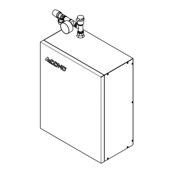
Hydromodul HM
Installation manual
1/17
PROVOZOVNA: Sažinova 1437
399 01 Milevsko
Štěrboholská 1434/102a
102 00 Praha 10
revize: 02.02.2023
Advertisement
Table of Contents

Subscribe to Our Youtube Channel
Summary of Contents for Acond Hydromodul
- Page 1 02.02.2023 Tel.: 382 521 202 | E-mail: info@acond.cz | Servis: 601 373 073 | IČO: 27154505 | DIČ CZ27154505 | Bankovní spojení: 191623146/0300 Společnost je zapsána v oddílu B, vložka 9370 obchodního rejstříku vedeného u Městského soudu v Praze. | www.acond.cz...
-
Page 2: Table Of Contents
Safety valve check ........14 Components ..........6 Disconnect from the mains ...... 15 Installation location ......7 Cleaning ........... 15 Hydromodul ..........7 E-heater thermostat reset ....15 6.1.1 Electrical preparation ....... 8 Warranty .......... 16 Indoor room unit ......... 8 Service.......... -
Page 3: Explanation Of Symbols, Documentation Validity
© 02/2023 Copyright ACOND a.s. 2 Important information The hydromodule is a separately functional unit, but it can also be installed with an Acond heat pump if the conditions specified in this manual are met The device must not operate persons with limited mental abilities or lack of experience and knowledge (including children) unless they are under supervision of instructed persons responsible for their safety. -
Page 4: Installation
• Gas fire extinguisher 3 Models According to the possibility of connecting a heat pump of the Acond brand, the models of the Hydromodule are distinguished, which differ only in the electrical part of the Hydromodule. For the given model, it is necessary to prepare the correct protection in the home switchboard and bring the correct cables, see the attached diagrams. -
Page 5: Parameters
Hydromodul Hydromodul PRO-R SP PRO-R SP 1~N/PE/230V/50Hz; B50A Hydromodul Grandis-N Grandis-N 3~N/PE/400V/50Hz; B20A Hydromodul Grandis-N SP Grandis-N SP 1~N/PE/230V/50Hz; B40A Hydromodul Grandis-R Grandis-R 3~N/PE/400V/50Hz; B20A Hydromodul Grandis-R SP Grandis-R SP 1~N/PE/230V/50Hz; B50A 4 Parameters The Hydromodule is a compact solution for heating water, heating water circulation and at the same time, after connection to an indirect hot water tank, it heats it to the desired temperature. -
Page 6: Internal Scheme
Hydromodul 5 Internal scheme The internal diagram shown in the following picture is for illustrative purposes only. Installation manual... -
Page 7: Components
Hydromodul Obrázek 1 Vnitřní schéma 5.1 Components Components at positions 4, 5 and 6 can be replaced with any equivalent parts suitable for the stated maximum operating pressure and temperatures. Z Heating water can leak out of the pressure relief valve in the event of a malfunction, so a hose leading to the drain must be connected to it. -
Page 8: Installation Location
Hydromodul 6 Installation location 6.1 Hydromodul The utility room must be spacious enough and dry. The air temperature must be between 10°C and 35°C and the relative humidity should not permanently exceed 70%. Under no circumstances must the Hydromodule be installed on walls made of... -
Page 9: Electrical Preparation
Hydromodul 6.1.1 Electrical preparation The electrical connection is made from the bottom side, where leave a free cable length of at least 2m. The cables to be brought in are given by the diagrams annexed to this document. 6.2 Indoor room unit The indoor C-ID room unit shall be placed in a heated reference room. -
Page 10: Mounting Of The Hydromodulu
Hydromodul 7.2 Mounting of the Hydromodulu The anchor profile, which is attached inside the Hydromodule, is mounted to the wall by means of 2 dowels and screws. Holes for screws are ø7mm. Subsequently, the Hydromodule is hung on this profile. - Page 11 Hydromodul The hydraulic connection changes according to customer requirements, the parameters of the heated building and the selected optional equipment. For an example of hydraulic connection, see the following figure. 7.3.1 Safety valve A hose/pipe is connected to the safety valve, which is located above the Hydromodule covers, and is led below the level of the Hydromodule.
-
Page 12: Mandatory Hydraulic Components
Hydromodul 1.1 Pokojov jednotka 2.1 Bojler 2.2 Aku n doba - z sobn k topn vody Ve ker vodn potrub mus b t (dle pot eby) Otopn soustava dle pot eby dn odvzdu n no 2.3 Pomocn el. zdroj tepeln energie pomoc odvzd. -
Page 13: Electrical Wiring And Commissioning
Hydromodul 7.5 Electrical wiring and commissioning It is electrically connected using the diagrams supplied with this manual. The electrical wiring procedure is as follows: 1. Switch off the heat pump circuit breaker in the home switchboard. 2. By measuring the power cables, make sure that they are really disconnected from the electrical. -
Page 14: Cleaning After Installation
Hydromodul 6. Connect the Ethernet cable to the lower slot on the control unit. 7. Connect the notebook to the middle Ethernet slot on the control unit. 8. Switch on the heat pump circuit breaker in the home switchboard. 9. Commissioning the Hydromodule with AcondThem control. Regulation guidance can be downloaded from the website https://acond.cz/tepelna-cerpadla/servis/... -
Page 15: Circulation Pump Operation And Maintenance
Hydromodul 9.1 Circulation pump operation and maintenance A circulation pump is a component that has possible replacements according to market availability. The model of the circulation pump is written on its label. If one of the possible substitutes is used, visit the manufacturer's website to find the operating instructions for the circulation pump. -
Page 16: Disconnect From The Mains
Hydromodul Be careful, hot water may flow out of the valve. 9.4 Disconnect from the mains First, use the AcondTherm regulation to switch off the device and then disconnect the device from the main by switching off the circuit breaker in the main home switchboard. -
Page 17: Warranty
6. Again, perform diagnostics. If a red alarm appears after manually switching on the heating rod, the heating rod is closed. 7. Cover the Hydromodul. 11 Warranty The manufacturer provides a warranty for the product within the period, performance and under the conditions specified in the warranty card.
Need help?
Do you have a question about the Hydromodul and is the answer not in the manual?
Questions and answers