Advertisement
Quick Links
Advertisement

Related Manuals for QABA 340-004


Summary of Contents for QABA 340-004
- Page 1 INffa076_US 340-004 READ AND SAVE THIS INSTRUCTION FOR FUTURE USE ASSEMBLY INSTRUCTION...
- Page 2 PACKING DETALS:TOTAL 2 BOXES BOX-1/2 BOX-2/2 PARTS PARTS Hardware Kit...
- Page 4 Beech sticks Adjusting rod Support Rod Main anchor Lengthened foot Bottom support Rod +1 (spare) M12 * 30 screw with flat M10 plum screw M18 spring latch pad and spring pad +1 (spare) M6 plastic source screw M12 * 80 screws with flat pad M8 * 50 round head screw and spring pad and M12 nut with M8 cap-typed nut...
-
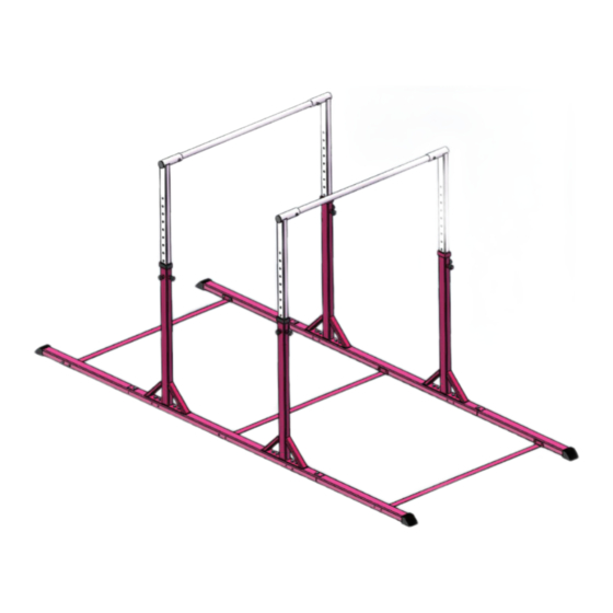
Page 5: Installation Diagram
INSTALLATION DIAGRAM: 1.Place part D then install part E on both ends of part D respectively, and lock it by J;... - Page 6 2. Install part C on part D according to the required position, connect and lock it with I; 3. Install part F on parts D&E, connect and lock with K;...
- Page 7 4. Connect parts A and B with L and lock it, put it into Part C, adjust the ideal height and use G and H to lock it; 5. When you need to adjust the height, you can loosen G and H, and pull B to adjust height;...
Need help?
Do you have a question about the 340-004 and is the answer not in the manual?
Questions and answers