Advertisement
Quick Links
z
o
&,
F
@
o
t
The
product is a component
ofthe
JABLOTRON 100
system.
/t
serves for
poweing
and
controlling
electric
door
locks and
access
control
units from the
system BUS.
Duing
lock
operation
the included
bafteries
supply enough current to open an electric
lock,
duing
the leading edge of the
cunent
pulse.
The
JA-120N
can be
mounted practicaily
in
any
place
where
it
is
difficult
to
install
an external
power
supply to
control
an
electric lock
This module reacts
to
control
panel
PG
outputs
or
it
can
be
activated
by
a
release
key
connected
to
the
lN
tetminal.
The
module
is
supplied
inside
a
JA-190PL installation
box.
It
should
be
installed
by
a
trained technician
with
a
valid
ceftificate
issued
by
an authorised distributor.
lnstallation
Figure
1:
1
-
rechargeable
bafteies;
2
-
DOOR output indicator,
3
-
JA-100
BUS activity
indicator;
4
-
lN input activation indicator;
5-
LEARN
(enrollment)/ tamper contact;
6
-
BUs
terminals;
7
-
input and output
terninals
(Yo)
1.
We
recommend removing
the
module's PCB
to
avoid
unwanted damage during installation. Punch
the
holes
into
the
JA-190PL rear plastic part
for
cables.
Insert
the
BUS
cables
and
attach
the
plastic base onto
the
required
place
using screws.
^4,
When
connecting the
modute
to
the
ZE\
system
BUS,
always
switch the
power
off.
2.
Put
the
PCB back onto
the
olastic base. Connect
the
BUS
wires
to the
BUS terminals (6) and
the
cables
for
door
lock
control
to
the l/O
terminals
(7).
Always
use
CC-01
(Jablotron)
cable
for
connecting
to
the
control panel.
For
connection
of
the door
lock
or the external power supply
use
cables
with
an adequate
cross-section.
Terminal descriotions:
DOOR
-
+
t2V
outout for
electric
lock control
COM,
lN
-
Input
terminals
serving
for activation
by the
release button
(reaction
NO/NC).
GND
-
Common
terminal for
an
external
power
supply and for
electric door
lock control
+12V
-
Input
terminal for
an
external
power
supply
(the DE 06-12 is recommended)
Proceed according
to the
control panel installation
manual.
Basic procedure:
a.
When the
system
has
been
turned on then the
yellow
LED (3)
flashes
and it
indicates
the
module
has not been
enrolled
to the system yet.
b.
Using F-Lrnk
software, select
the required
position in
the
Devices window
and
launch enrollment mode
by clicking
on
the
Enroll
ootion.
c.
Press
the LEARN/TAMPER
(5) button
in
the
module
-
the module
is
thus enrolled to the system and the
yellow
LED indicator goes off.
Put
the
cover on the module.
Setting the
module properties
The
module properties can
be set in the Devices
window of
the
F-Link
software.
When
at the
module position, use
the
lntemal
setfings.option to
open
a
dialogue wlndow where
you
can set the
following
options:
LED
indication
-
Enable
/
disable optical indication
by
the
red
LED (4) of
triggering the
lN input.
The JA-120N
BUS module for
electdc door
locks
1
I
2
DOOR reacts
to
PG
status
-
Determines which PG outout or
outDuts
the
module reacts to.
Minimum
PG
switching
time
-
Sets
the
minimum
switching
time of the
DOOR output regardless
of the PG
output
impulse
length.
Maximum
PG
switching time
-
Sets
the
maximum
switching
time
of
the
DOOR output regardless
of the PG
output
impulse
length. When
the lN
input
is
triggered
the
DOOR output
is
always
switched
on for
that
predefined time.
Nofe:
the
minimum switching
time can't be
set
to a
higher
value than
the
maximum value.
The
F-rrnk software adiusts
its
offer
of
those
parameters
dynamically.
lN
inout ootions:
Disabled
The module
doesn't
react
to lN
inpul
activation
Manual
control
Triggering the lN
input
switches
on
the
DOOR
terminal for
a predefined
iime according to the
"lvlaximum PG
switching
time"
System
Triggering the lN input
causes
the
control
panel
to
react according to
the
reaction set
at
the module's
position
in
F-rink (Reaction
column)
lN input inverted:
Determines
the logic
of
the lN input
NCINO.
The
input
is
not balanced and is
set
to
NO
as
a factory default
(option disabled).
DOOR
input
inverted: This
option inverts
the
logic
of
the
DOOR
output
for e.g. reverse locks. When the option
is checked
and
the
input
is in
standby
a
voltage occurs
on
the
DOOR
output.
/Vofei
for
correct functioning it is necessary
to
power
the
module
fiom
an extemal power supply
(for instance:
the
DE 06-12).
Blocking
the
lN
input
by
section: This
option can block
the
lN
input by
setting
the
section
to
which
the
module
has
been
enrolled.
The
option is only available
if
Manual control of
the
lN
input
has been enabled.
Function button during communication
fault:
This
option
keeps
the
module active,
with
backup control
of the
DOOR
output
by
lN
input triggering
when
communication
with
.the
conirol
oanel
is
lost.
Unlock
the
IN
input
during
a fire
alarm: This
parameter
unlocks the lN
input
during
a
fire alarm even though
blocking
the
lN
input
by
the
section
has
been
enabled.
This
option
is
available only
if
the function 'Blocking
the
lN input by section" is
enabled.
Triggered tamper: This
parameter
can
disable
the
tamper
contact for
cases when
the module
is
going to be installed
inside
a
different
box or into a box
with different tamper
protection.
t\Iofe.'
The
module
is
designed
for
use
with very
high quality
N|MH batteries (Eneloop 1.2V
AA ones
supplied)
in
a
positive
operational temperature range. NiMH batteries have unsuitable
behaviour
in
a
negative operational temperature range so
in
this
case
we recommend
using NiCd
batteries
in
the
module.
Apolication recommendation:
We
recommend using
the
module
with door
locks
complying
with the following
parameters:
-
Standard locks
12
V
DC
/ max.
300
mA
-
Reverse locks
12
V
DC
I
17O
mA (for reverse door
locks
it
is necessary to
plug in
an
external power supply,
for
example
the
DE 06-12)
4.
f
-9.
z
c
q)
63.
;E:
\u (E6
=;E
r >:;
<YE
J-{
<Pg
zxB
C)fit:
;7s=
L^l
n*q)
v6E
J*-
m
",?
<6K
'1
0-
c)
ei
I
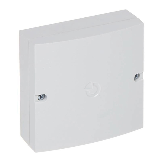
Figurc 2:
JA-190PL
installation
box dimensions
M1Y57700
Advertisement


Need help?
Do you have a question about the JA-120N and is the answer not in the manual?
Questions and answers