
Subscribe to Our Youtube Channel
Related Manuals for Gainlab Audio bishop

Summary of Contents for Gainlab Audio bishop
-
Page 2: Personal Injury
PLEASE NOTE THAT THE GLA-MP1 BISHOP IS INTENDED FOR PROFESSIONAL USE. IT’S NOT A CONSUMER ELECTRONIC DEVICE. ITS INSTALLATION AND USE REQUIRE CERTAIN PROFESSIONAL SOUND ENGINEERING KNOWLEDGE AND SKILLS. LACK OF THIS KNOWLEDGE MAY RESULT IN MALFUNCTION, DAMAGE OR PERSONAL INJURY. - Page 3 ■ If the device has been exposed to rain or other moisture, ■ If the device does not operate normally ■ Do not connect the appliance to a mains socket to which an electrical appliance controlled by an inverter, switching power supply (eg.
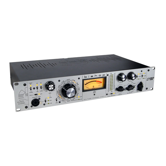
- Page 4 PREAMP AUX. PREAMP SECTION TONE CONTROL SECTION INPUT SELECTION DYNAMICS SECTION INTRODUCTION BISHOP All Tube Channel Strip is a fully symmetrically designed recording channel with an All Tube system, featuring a two-stage amplification, dynamic processing, tone control options. Symmetrical in nature, it does not asymmetrically alter the received balanced signal.
- Page 5 Gain scale, handles amplification ranging from +6dB to +40dB and can be accessed by setting the Gain switch to the lower position. The external scale, known as the High Gain scale, manages amplification between +26dB and +60dB and is accessible by toggling the Gain switch to the upper position.
- Page 6 NOTE: GROUND THE RECEIVING SIDE If the Bishop has a microphone connected to it with an external power supply, there is a possibility that a so-called ground loop may form between the Bishop's power supply and the external microphone's power supply, which can have an undesirable impact on the signal-to- noise ratio.
- Page 7 The compressor can be activated or deactivated using the switch located below the reduction meters. The compressor in the Bishop utilizes optical compression, employing Light Dependent Resistors (LDRs) for dynamic control, similar to units like the LA2A or CL1B. While most dynamics processors...
- Page 8 This can be achieved using the SC.Link connector located on the back of the Bishop, using an asymmetric Jack-Jack cable. In terms of practical implementation, it's advisable to proceed as follows:...
- Page 9 Located below the tone control section is the rotary switch for the output attenuator. This allows us to create a -12dB attenuation in 5 steps on the Bishop's output. This can often be useful, for instance, to compensate for the gain reduction caused by the compressor.
- Page 10 TONE CONTROL SECTION On the top right side of the Bishop, you'll find the controls for the filter section, which determine the tonal characteristics of the sound processed by the Bishop. The HPF switch activates a simple high-pass filter designed to eliminate potential muddiness in the low-frequency range.
Need help?
Do you have a question about the bishop and is the answer not in the manual?
Questions and answers