Table of Contents
Advertisement
I NS T RUCT I ON MANUAL
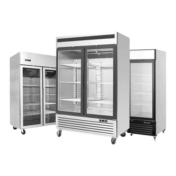
D I S P L A Y F R I D GE
P l e a s e r e a d t h e u s e r ' s ma n u a l b e f o r e y o u u s e t h i s p r o d u c t .
I f y o u r e q u e s t u n n e c e s s a r y s e r v i c e s , y o u ma y w a s t e mo n e y .
T h u s , f i x s i mp l e t r o u b l e s b y y o u r s e l f w h i c h y o u h a v e f o u n d .
Advertisement
Table of Contents

Subscribe to Our Youtube Channel
Related Manuals for Atosa MCF8601GR


Summary of Contents for Atosa MCF8601GR
- Page 1 I NS T RUCT I ON MANUAL D I S P L A Y F R I D GE P l e a s e r e a d t h e u s e r ’ s ma n u a l b e f o r e y o u u s e t h i s p r o d u c t . I f y o u r e q u e s t u n n e c e s s a r y s e r v i c e s , y o u ma y w a s t e mo n e y .
-
Page 2: Table Of Contents
C o n t e n t : 1 . T e r ms a n d c o n d i t i o n s ......... . 2 2 . -
Page 3: Terms And Conditions
� i ! i . D 1 TERMS AND CONDITIONS: Refrigeration 2 YEAR WARRANTY All claims for parts or labor must be made directly through Atosa.AII claims must indude: model number ihe unit, the serial number, proof date installation, and all pertinent information supporting of purchase, the alleged defect.In case... - Page 4 Additional Three Year Compressor Warranty In addition to the two (2) year warranty stated above, Atosa warrants its sealed compressor to be free from defects in both material and workman ship under normal and proper use and maintenance service for a period of three (3) additional years from the date of original installation, but not to exceed five (5) years.
- Page 5 What is Not Covered by This Warranty Atosa 's sole obligation under this warranty is limited to either repair or replacement of parts. subject to the additional limitationsbelow. This warranty neither assumes nor authorizes any person to assume obllgatlons other than those expressly covered by thiswarranly.
- Page 6 In such areas. •1 n some cases, a 25% restocking fee may be charged lo a buyer for returned nems. *Atosa may at any time modify our equipment in order provide and insure a superior product. Change is sometimes necessary to keep up with todays high standards in our industry.
-
Page 7: Preface
2. Preface Please read instructions before using this appliance. IMPORTANT SAFETY INSTRUCTION • To reduce the risk of fire, electric shock, or injury to persons when using your product, basic safety precautions should be followed, including the following. • This appliance must be properly installed and located in accordance with the Installation Instruction before it is used . - Page 8 • Do not disconnect by pulling on the cord. Always disconnect by grasping and pulling on the plug top. • Do not pull out the cord or touch the power plug with wet hands. Clean water or dust from the power plug and insert it with the ends of the pins securely connected.
- Page 9 ---11.- Warning: Risk of fire / flammable materials CAUTION: RISK OF FIRE AND EXPLOSION WITH FLAMMABLE REFRIGERANT R290 . .& If you need the electronic version instruction manual, please ask the manufacturer or its service agent .& Max. Load of shelf is 176 LBS. This instruction manual provides all the necessary information regarding: .&...
-
Page 10: Use Of The Equipment
3. Use of the equipment The refrigerator are for preserving fresh perishable foodstuffs, with an in-built refrigerated unit. Do not utilise the equipment to store medical supplies. The optimum operational ambient temperatures are between +1o· c +4o·c. 4. Technical features The refrigerator is a ventilated system, the evaporator is in a separate insulated box on the top. -
Page 11: C O N T R O L U N I
6. Control unit The refrigerator is command from a "digital control unit" and a "main switch pilot light" in the top panel of the refrigerator. The "main switch pilot light" is for turning on the power supply. The red pilot light comes on to indicate that the unit is connected to the main electricity and to start work. -
Page 12: I N S T A L L A T I O N P R O C E D U R
8. Installation procedure A Place the refrigerator in the coolest and best ventilated part of the room. Don' t install the refrigerator in the near of heat and direct sunlight sources. A Remove the straps securing the cardboard packing Remove the cardboard. Covering Remove the PET protection film A Clean the refrigerator with mild detergent and then dry it with a soft cloth. -
Page 13: C L E A N I N
• the electric system to which the refrigerator is sized to cater for the rated electric output of the buffet unit being installed • the electronic system to which the refrigerator is connected is made in compliance \/Vith current standard requirements •... -
Page 14: C L E A N I N G T H E I N S I D E O F T H E R E F R I G E R A T O
Cleaning the inside of the refrigerator: Clean the inside area min. each month with a detergent suitable for use with foodstuffs. Cleaning the condenser: For an efficient operation of the refrigerator it is advisable to c lean the condenser regularly approx. every 4 months with a dry brush or vacuum cleaner. - Page 15 13. Configuration Sketch Map Top Mount Serise Reach-Ins Bottom Mount Serise Reach-Ins IAiial � � � 1. Power switch 2. Microcomputer controller 3. Compressor 4. Evaporator 5. Evaporator fan 6. Condenser fan 7. Condenser 8. Downcomer for condensing water 9. Lamp 1.
- Page 16 3. Microcomputer Controller Operation lnstru ction: 4. Microcomputer panel sketch map, meanings of running indicator light and LED showing. I� SET To display target set point, in 1':1,-�--· ..,J l--� - --------=--- - �-·· programming mode it selects a parameter (Mod.
-
Page 17: T E C H N I C A L P A R A Me T E R
9 . H o w t o c h a n g e a p a r a me t e r v a l u e T o c h a n g e t h e p a r a me t e r ’ s v a l u e o p e r a t e a s f o l l o w s : E n t e r t h e P r o g r a mmi n g mo d e b y p r e s s i n g t h e k e y s f o r 3 s ( “... - Page 18 T a b l e o f f u n c t i o n s a c t i v a t e d b y t h e b u t t o n s T a b . 2...
- Page 20 . T e c h n i c a l P a r a me t e r s Top Mount Reach-Ins MCF8601GR -8~-1 R290 28.7×33.3×81.3...
- Page 21 Bottom Mount Reach-Ins MCF8701GR -8~-1 R290 27×31.5×84 19.1 MCF8702GR -8~-1 R290 39.5×31.5×84 28.5 MCF8703GR -8~-1 R290 54.5×31.5×84 44.77 MCF8703ES -8~-1 R290 54.5×31.5×84 44.77 MCF8704GR 115/208-230 1360 -8~-1 R290 81.9×31.5×84 67.99 MCF8705GR +33~+45 R290 27×31.5×84 19.1 MCF8706GR +33~+45 R290 39.5×31.5×84 28.5 MCF8707GR +33~+45 R290...
- Page 22 MCF8721GR -8~-1 R290 54.5×31.5×84 43.46 MCF8721ES -8~-1 R290 54.5×31.5×84 43.46 MCF8722GR +33~+45 R290 27×31.5×84 19.39 MCF8723GR +33~+45 R290 54.5×31.5×84 43.95 MCF8724GR +33~+45 R290 81.9×31.5×84 69.54 MCF8725GR +33~+45 R290 24.3×24.1×74.5 11.1 MCF8726GR +33~+45 R290 24.3×24.1×61.5 MCF8727GR +33~+45 R290 54.5×29.2×84 44.85 115/208-230 MCF8728GR 1360 -8~-1...
-
Page 23: O F F I C I A L A P P R O V A L A N D R U L E
OF F I C I A L A P P R OV A L A ND R UL E S C O N F O R MS T O U L S T D . 4 7 1 C E R T I F I E D T O C S A S T D . C 2 2 . 2 N O . 1 2 0 C O N F O R MS T O N S F / A N S I S T D . - Page 24 W081106603 version number 20200730...
Need help?
Do you have a question about the MCF8601GR and is the answer not in the manual?
Questions and answers