
Related Manuals for Moretti Design MONODESIGN 60


Summary of Contents for Moretti Design MONODESIGN 60
- Page 1 WOOD USE AND MAINTENANCE MANUAL MONODESIGN 60 - 70 - 80 - 90 - 120 LATODESIGN 60 RH - 90 RH LATODESIGN 60 LH - 90 LH TRIODESIGN 90...
-
Page 3: Table Of Contents
TABLE OF CONTENTS 1 - Introduction 2 - General warnings 3 - Warranty conditions 4 - Technical and dimensional characteristics 4.1 - Technical characteristics 4.2 - Technical Drawings 5 - Safety warnings 6 - Product identification and technical characteristics 7 - Installation 7.1 - Waste disposal 7.2 - Unpacking and sliding unit movement 7.3 - Minimum safety distances... -
Page 4: Introduction
1 - INTRODUCTION Dear customer, thank you for choosing a MORETTI DESIGN product, a cutting-edge product in the field of wood- burning fireplaces for heating. The great attention to detail during the design phase, the use of advanced technology, the quality of the materials and the extreme care taken during the processing phase, are the best guarantee of an efficient, functional, safe and suitable product to fully meet your heating needs. -
Page 5: Warranty Conditions
Parts and materials subject to wear and tampering are excluded from the warranty. Masonry works of any kind, inclu- ding those for disassembling and reassembling the product, are excluded. In the event of a malfunction, the firebox will not be replaced but repaired. Moretti Design shall not be held responsible for incorrect assembly or unauthorised tampering and interventions. -
Page 6: Technical And Dimensional Characteristics
4 - TECHNICAL AND DIMENSIONAL CHARACTERISTICS 4.1 Technical characteristics MONODESIGN LATODESIGN TRIODESIGN Description U.M. 60 RH 60 LH 90 RH 90 LH 19.50 21.80 23.00 24.60 24.60 19.50 19.50 24.60 24.60 24.60 Thermal power input 17.00 19.00 20.00 21.40 21.40 17.00 17.00 21.40... - Page 7 MINIMUM DISTANCE WITHOUT INSTALLATION OF VENTILATION KIT (WITH STANDARD FOOT) MINIMUM DISTANCE WITH VENTILATION KIT INSTALLATION ART. MORKV720 (OPTIONAL) Accessory not supplied. Place a thickness of the height of 150mm to position the MORKV720 venti- lation kit box...
-
Page 8: Technical Drawings
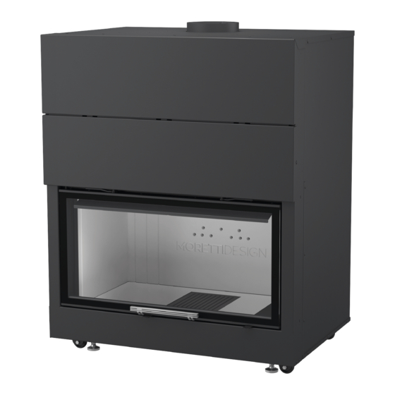
4.2 Technical drawings MONODESIGN 60 MONODESIGN 70 MONODESIGN 80... - Page 9 MONODESIGN 90 MONODESIGN 120 LATODESIGN 60 RH...
- Page 10 LATODESIGN 60 LH LATODESIGN 90 RH LATODESIGN 90 LH...
-
Page 11: Safety Warnings
TRIODESIGN 90 5 - SAFETY WARNINGS WARNING!!! For the correct use of this appliance and its electrical components, the instructions given in this manual must always be observed. WARNING!!! This appliance CANNOT be used on a shared flue WARNING!!! Installation, electrical connections, verification of operation, maintenance and repairs are ope- rations that must be carried out exclusively by qualified personnel WARNING!!! This appliance must only be used for the purpose for which it was designed and built. -
Page 12: Product Identification And Technical Characteristics
6 - PRODUCT IDENTIFICATION AND TECHNICAL CHARACTERISTICS The standard range of MORETTI DESIGN vented burners includes 14 different models. To allow the identification of the model and the related technical data, a plate like the one shown below is placed on each firebox. -
Page 13: Minimum Safety Distances
Sliding unit movement To allow the sliding unit to be closed, unscrew the door locking screw (fig. 2) only on the MONODESIGN 60, 70, 80, 90 & 120 models The door locking screw prevents any vibrations during the transport of the firebox from causing the glass to break. -
Page 14: Flue Pipe Connection
Moretti Design srl is not responsible for damage to persons, animals or property resulting from failure to comply with the safety distances indicated above, or for installations that do not comply with local, regional, national and European regulations. -
Page 15: The Chimney
7.5 - THE CHIMNEY The chimney allows the forced draft of the fireplace, that is, the evacuation of fumes. When we talk about the height of the chimney, we refer to the evacuation rings, excluding the size of the final rain cap. A suitable dimensioning of the chimney is essential for a correct forced draft. -
Page 16: Air Intakes
Table 1 α Distance between Minimum height out- roof axis (ridge) and Roof slope let from the roof(h Reflux zone height upstream side of the minimum) chimney 15° 1.85 m 1.00 m 0.50 m 30° 1.50 m 1.30 m 0.80 m 45°... -
Page 17: Intakes For Heating Air
Drill two holes in the wall communicating with the outside (or with a sufficiently ventilated environment): one suitable for the Fig. 8 passage of the 8 cm aluminium flexible pipe and another 15 cm in diameter inside the support structure (see figure 8). After cor- rectly positioning the appliance as described above, insert the manifold into the section of aluminium flexible pipe and secure it with a hose clamp, then insert the section into the hole pre-... -
Page 18: Installation Of Ventilation Kit (Optional Item Morkv720)
7.7 - INSTALLATION OF VENTILATION KIT (OPTIONAL art. MORKV720) All MORETTI DESIGN fireboxes allow the installation (optional) of a ventilation kit that makes it possible, through flexible pipes, to bring hot air also into adjacent rooms and/or away from the fireplace (heat distribution by forced convection), thus ensuring the same comfort of the installa- tion environment. -
Page 21: Centrifugal Fan
7.7.2 - CENTRIFUGAL FAN The fan sucks the air from the side and, after passing it through the heating areas of the firebox, sends it to the environment whose air is to be heated. The fan must be inserted into the appropriate motor box located at the bot- tom of the firebox. -
Page 22: Hot Air Ducting
WARNING: For the installation of the control unit, rely on qualified personnel. MORETTI DESIGN is not liable for any errors or tampering that may compromise its functionality (e.g. failure as a result of incorrect connection to the mains, opening and changes to the electronic board). -
Page 23: Installation Of Thermostatic Probe
7.7.6 - INSTALLATION OF THERMOSTATIC PROBE The presence of a thermostatic probe allows the fan to start and turn off automatically: it gives the consent to start the motor when it senses the threshold hot air temperature set by the manufacture, and turns it off when it falls below this value. - Page 24 MONODESIGN 60 LATODESIGN 60 LH LATODESIGN 60 RH MONODESIGN 70...
- Page 25 MONODESIGN 80 MONODESIGN 90 LATODESIGN 90 LH LATODESIGN 90 RH...
-
Page 26: Removing The Upper Deflectors
TRIODESIGN 90 MONODESIGN 120 7.8.1 - REMOVING THE UPPER DEFLECTORS To carry out the general cleaning operations, paragraph 5.5.2, it is necessary to remove some internal elements of the appliance, taking great care when handling the vermiculite elements. To remove the deflectors 2, 3, 4, 5 & 6 fol- low the pictures below. -
Page 27: Use And Maintenance Of The Firebox
PHASE PHASE PHASE PHASE PHASE 8 - USE AND MAINTENANCE OF THE FIREBOX Warning: It is suggested to ventilate the room at the first ignition and not to stay near the fireplace, to eva- cuate any odours and/or fumes emitted by the paint during drying and curing due to heat. The odours and/ or fumes will disappear after about 4 hours of operation, however, remembering that they are not harmful to health. -
Page 28: Air Registers
Some firebox models are equipped with the new FIRE TECH MODE lever. (figure 15-b). The intuitive lever gives you complete control of the airflow and ignition of the Moretti Design fireplace. This innova- tive feature allows you to choose between different adjustment options:... -
Page 29: First Ignitions
The X Button: Allows shutdown With the Fire Tech Mode, you will have the opportunity to customise the experience of your Moretti Design firepla- ce, adapting it to your specific needs and enjoying optimal thermal comfort Fig. -
Page 30: Sliding Door Adjustment
Fig. 19 8.4 - SLIDING DOOR ADJUSTMENT In all models of the MORETTI DESIGN range, the screws for adjusting the sliding door are placed in front of the guides. MODELS: MONODESIGN 60, MONODESIGN 70, MONODESIGN 80, MONODESIGN 90, MONODESIGN 120, LATODESIGN 60 RH, LATODESIGN 60 LH, LATODESIGN 90 RH &... -
Page 31: Daily Use
MODEL: LATODESIGN 60 RH, LATODESIGN 60 LH, LATODESIGN 90 RH & LATODESIGN 90 LH. • The screws of the sliding door are located: 3 (three) inside the firebox and 3 (three) outside as shown in fig. 21- a / 21-b •... -
Page 32: Cleaning And Maintenance
• The appliance must not be used as an incinerator, but must be used exclusively in the ways and with the fuels indicated in this manual. • During normal operation, the surfaces of the firebox, especially the glass, reach high temperatures and can cause touch burns. -
Page 33: Cleaning Of The Fire Pit
In case of faults that require the replacement of some parts of the hearth, it is recommended to use only original spare parts. The use of non-original spare parts entails the immediate forfeiture of the warranty and the non- recognition by Moretti Design of any damage caused to persons, animals or property. 8.6.3 - CLEANING OF THE GLASS It should only be done with a cold fireplace, using special products with paper or a soft cloth. -
Page 34: Supplied Keys (Cold Hand)
- TRIODESIGN 90 The opening is side-hinged, and is done by pulling out the levers that are on the corners of the door between the short side and the long side using the supplied key. Pulling the levers unhooks the door on the short side and it can be opened for cleaning (from fig. - Page 36 REGISTERED OFFICE AND SHOWROOM: Contrada Tesino 50 63065 Ripatransone (AP) ITALY www.morettidesign.it Moretti Design assumes no responsibility for any errors in this brochure and is free to change the characteristics of its products without notice REV. 009/2023 ENG...
Need help?
Do you have a question about the MONODESIGN 60 and is the answer not in the manual?
Questions and answers