Table of Contents
Advertisement
Quick Links
Advertisement
Table of Contents

Summary of Contents for SKYSMotor 3DM2283T
- Page 1 User’s Manual 3DM2283T Fully Digital Stepper Drive www.skysmotor.co.uk...
-
Page 2: Table Of Contents
Full Digital Stepper Drive 3DM2283T Table of Contents 1. Introduction, Features and Applications........................1 Introduction................................1 Features..................................1 Applications................................1 2. Specifications................................1 Electrical Specifications (Tj = 25℃/77℉)......................1 Operating Environment and other Specifications....................2 Mechanical Specifications (unit: mm [1inch=25.4mm])..................2 Elimination of Heat..............................2 3. - Page 3 Full Digital Stepper Drive 3DM2283T 12. Frequently Asked Questions............................9 Problem Symptoms and Possible Causes........................ 9 www.skysmotor.co.uk...
-
Page 4: Introduction, Features And Applications
Its motor auto-identification and parameter auto-configuration feature offers quick setup to optimal modes with different motors. Compared with traditional analog drives, 3DM2283T can drive a stepper motor at much lower noise, lower heating, and smoother movement. Its unique features make 3DM2283T an ideal choice for high requirement applications. -
Page 5: Operating Environment And Other Specifications
Full Digital Stepper Drive 3DM2283T Operating Environment and other Specifications Cooling Natural Cooling or Forced cooling Environment Avoid dust, oil fog and corrosive gases 0℃ - 50℃ Ambient Temperature Operating Environment Humidity 40%RH - 90%RH 45℃ Max Operating Temperature 10-55Hz/0.15mm... -
Page 6: Pin Assignment And Description
Full Digital Stepper Drive 3DM2283T 3. Pin Assignment and Description The 3DM2283T has two connectors, connector P1 for control signals connections, and connector P2 for power and motor connections. The following tables are brief descriptions of the two connectors. More detailed descriptions of the pins and related issues are presented in section 4, 5, 9. -
Page 7: Rs232 Communication Port
The 3DM2283T can accept differential and single-ended inputs (including open-collector and PNP output). The 3DM2283T has 3 optically isolated logic inputs which are located on connector P1 to accept line drive control signals. These inputs are isolated to minimize or eliminate electrical noises coupled onto the drive control signals. -
Page 8: Connecting The Motor
6. Power Supply Selection The power supply voltage can work normally between the voltage range specified by the driver. The 3DM2283T is directly powered by AC. It is recommended that the user use the highest voltage lower than the driver's specified voltage to avoid the grid fluctuation exceeding the driver voltage operating range. -
Page 9: Current Settings
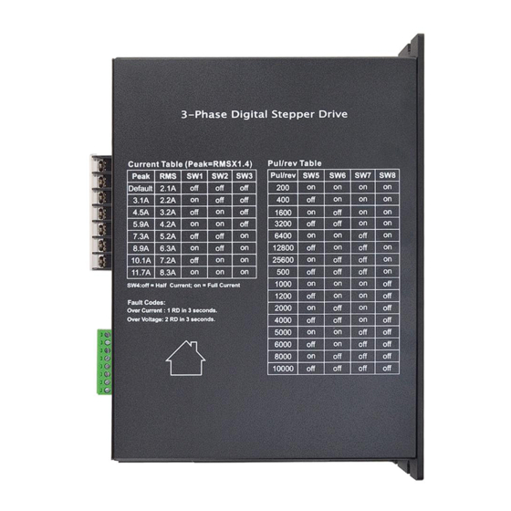
Full Digital Stepper Drive 3DM2283T 10000 Current Settings For a given motor, higher drive current will make the motor to output more torque, but at the same time causes more heating in the motor and drive. Therefore, output current is generally set to be such that the motor will not overheat for long time operation. -
Page 10: Typical Connection
Full Digital Stepper Drive 3DM2283T up together. It is better to separate them by at least 10 cm, otherwise the disturbing signals generated by motor will easily disturb pulse direction signals, causing motor position error, system instability and other failures. -
Page 11: Protection Functions
Full Digital Stepper Drive 3DM2283T Figure 11: Sequence chart of control signals Remark : a)t1: ENA must be ahead of DIR by at least 5s. Usually, ENA+ and ENA- are NC (not connected). See “Connector P1 Configurations” for more information. - Page 12 Full Digital Stepper Drive 3DM2283T it to make it function properly after removing above problems. 12. Frequently Asked Questions In the event that your drive doesn’t operate properly, the first step is to identify whether the problem is electrical or mechanical in nature.
Need help?
Do you have a question about the 3DM2283T and is the answer not in the manual?
Questions and answers