Table of Contents
Advertisement
Quick Links
Advertisement
Table of Contents

Related Manuals for Moller Vacusat power


Summary of Contents for Moller Vacusat power
- Page 1 ® Vacusat power ® Vacusat power...
- Page 3 IMPORTANT READ CAREFULLY BEFORE USE KEEP THESE INSTRUCTIONS FOR FUTURE REFERENCE © Möller Medical GmbH All rights reserved. No part of this documentation may be reproduced or translated in any way whatsoever without prior written approval from Möller Medical GmbH. The status of the information, specifications and figures in these in- structions for use is indicated by the version number on the last page.
-
Page 4: Table Of Contents
® Vacusat power Table of contents Table of contents Table of contents ....................4 General safety information ................6 Explanation of safety symbols used ..............6 1.1.1 Symbols in the instructions for use ..............6 1.1.2 Symbols on the device ..................6 1.1.3 Additional symbols on the retail packaging ............. - Page 5 ® Vacusat power Table of contents 4.4.9 Assembling the storage tray ................30 Disassembly ..................... 30 4.5.1 Ending the suction procedure................ 30 4.5.2 Emptying the suction canister ............... 30 4.5.3 Disassembling hoses ..................31 4.5.4 Disassembling the overflow protection ............32 Use and operation ..................
-
Page 6: General Safety Information
® Vacusat power General safety information 1 General safety information 1.1 Explanation of safety symbols used Important information is indicated visually in these instructions for use. These indications are necessary to prevent hazards to patients and operating personnel, as well as to avoid dam- age and device malfunctions. -
Page 7: Additional Symbols On The Retail Packaging
® Vacusat power General safety information Device switched off Device switched on Foot switch Increasing the vacuum Reducing the vacuum 1.1.3 Additional symbols on the retail packaging Follow the instructions for use Catalogue number Batch code Packaging unit Use by YYYY-MM-DD (year-month-day) Sterilised using ethylene oxide Single sterile barrier system Double sterile barrier system... - Page 8 ® Vacusat power General safety information Not suitable for use with MRI Do not re-use Do not resterilise Fragile, handle with care Do not use if package is damaged Stacking restriction: stack may consist of max. 3 packages Keep dry Restriction on relative storage humidity Storage temperature limitation Manufacturing date...
-
Page 9: Explanation Of The Formatting Conventions Used
® Vacusat power General safety information 1.2 Explanation of the formatting conventions used In these instructions for use, different fonts are used to improve orientation. Font Bold Buttons in the operating instructions Italics Device options, buttons and references to chapter and sections in the running text. -
Page 10: Operator's Obligation To Exercise Diligence
® Vacusat power General safety information 1.4 Operator's obligation to exercise diligence The operator is responsible for the proper operation of the medical device. In line with the German Medical Device Operators Ordinance (MP BetreibV), the user must meet a wide range of obligations and also assume responsibility when handling medical devices within the framework of their activities. -
Page 11: Warning Notices
® Vacusat power General safety information 1.5 Warning notices • The products of Möller Medical GmbH may only be used if they are in a fully functional condition. Check for proper condition and full functionality before use. • ® No modifications to the Vacusat power are permitted. -
Page 12: Non-Product-Related Additional Equipment
® Vacusat power General safety information • These instructions for use do not include information on using components or accessories from other manufacturers. You must observe the instruc- tions for use of the relevant manufacturer. • Always observe the information on electromagnetic immunity (see appen- dix). -
Page 13: Single-Use
® Vacusat power General safety information 1.7 Single-use The re-use of a single-use product presents a potential risk of infection for the patient or operator. Contamination of the device may lead to injury, illness or death of the patient. Clean- ing, disinfection and sterilisation may affect essential material properties and product parameters to the extent that this leads to failure of the articles. -
Page 14: Intended Use
® Vacusat power Intended use 2 Intended use 2.1 Indications ® The Vacusat power is a powerful, low-noise suction device designed for continuous operation and is suitable for high flow and high vacuum. It can be used to suction tumescent solution, body fats, fat cells (secretions, blood and serous fluids) and the particles they contain from artificial body orifices and is intended for use on patients in: surgery, liposuction and aesthetic ®... -
Page 15: Product Description
® Vacusat power Product description 3 Product description All handling of the device requires precise knowledge and compliance with these instructions for use. These instructions do not replace the user training provided by the medical device consultant. The device must only be used by persons who have the required training or knowledge and experience (Sec. -
Page 16: Design
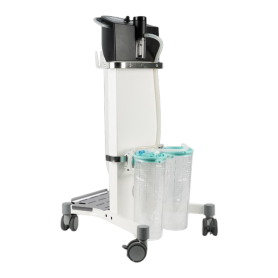
® Vacusat power Product description 3.1 Design Figure 1: ® Overview of the Vacusat power Suction pump Push handle Control panel Hose holder Vacuum meter Device rail Control lamp for foot switch Cover for bacteria filter ON switch Foot switch Control lamp for operation Hose coupling OFF switch... -
Page 17: Interface Description
® Vacusat power Product description 3.2 Interface description 3.2.1 Hydrophobic bacteria and virus filter It is not necessary to use a hydrophobic bacteria and virus filter if a suitable hydrophobic bacteria and virus filter is integrated for specific use in the secre- tion container when disposable bags are used. -
Page 18: Installation And Startup
® Vacusat power Installation and startup 4 Installation and startup Upon delivery, make sure that the boxes are not damaged. Check the Va- ® cusat power for damage. In the event that the product has defects, it should not be used and the supplier must be informed accordingly. 4.1 Transport and storage information A maximum of 3 cartons may be stacked for transport. -
Page 19: Unpacking The Device And Checking The Scope Of Supply
® Vacusat power Installation and startup 4.2 Unpacking the device and checking the scope of supply ® ® The delivery of the Vacusat power Vacusat power consists of one carton. Make sure that ® no parts remain in the packaging when unpacking the Vacusat power . -
Page 20: Commissioning
® Vacusat power Installation and startup 4.4 Commissioning ® The Vacusat power must be set up in a suitable place. Proceed in the following order: 4.4.1 Assembling the foot stand If the foot stands are incorrectly assembled there is a risk of tipping over. En- sure that there is a right and a left foot stand and that they are assembled correctly. - Page 21 ® Vacusat power Installation and startup Mounting the second foot stand • Place the green dot on the foot stand (1) on the green dot of the base device (2). • The longer section of the foot stand (3) points towards the floor. •...
-
Page 22: Assembling The Hose Holder
® Vacusat power Installation and startup 4.4.2 Assembling the hose holder The hose holders are screwed onto the right and left of the upper device rail. • Press the hose holder (1) with the open side facing upwards onto the device rail (2). -
Page 23: Overflow Protection / Hose Coupling
® Vacusat power Installation and startup 4.4.4 Overflow protection / Hose coupling ® The Vacusat power can be operated either with overflow protection or with a hose connector and downstream overflow protection. • ® Always operate the Vacusat power with connected overflow protection to protect the suction pump from over-suctioning. - Page 24 ® Vacusat power Installation and startup 4.4.4.2 Assembling the hydrophobic bacteria and virus filter in the mechanical overflow protection The overflow protection has the option of connecting a hydrophobic bacteria and virus filter after the mechanical overflow protection. It should be used if aerosols are present in the intake gas.
-
Page 25: Rail Clamp Interface
® Vacusat power Installation and startup 4.4.5 Rail clamp interface Containers can be attached to the rail clamp interface with a device holder. Attaching the rail clamp • Hang the rail clamp (1) on the device rail (2). • Secure the rail clamp with the retaining screw (3). - Page 26 ® Vacusat power Installation and startup 4.4.6.1 Installing the suction canister and disposable bag Installing the suction canister • Place the suction canister (1) upright in the rail clamp (2). • Connect the hose (3) with the angle connector (4) to the back of the suction canister.
-
Page 27: Installing Multiple Disposable Bags (In Series)
® Vacusat power Installation and startup Unfolding the disposable bag • The disposable bag is unfolded by a vacuum. • ® Switch the Vacusat power on while simultaneously pressing lightly on the middle of the lid (1). • When the disposable bag is correctly aligned, close the patient connector by hand (2) so the lid seals the suction can- Figure 20:... - Page 28 ® Vacusat power Installation and startup • Connect the suction canisters to each other with separate T-connectors and hoses. • Cut the hose to the required length with scissors. Figure 23: Hose coupling for use in series The T-connector and the vacuum hose are reusable and do not need to be replaced between procedures.
-
Page 29: Connecting/Disconnecting The Mains Cable
® Vacusat power Installation and startup 4.4.8 Connecting/disconnecting the mains cable • ® The mains plug must always be accessible so the Vacusat power can be disconnected from the power supply at any time. Connecting the mains cable • Check that the mains voltage is the same as the value indicated on the rat- ing plate (1). -
Page 30: Assembling The Storage Tray
® Vacusat power Installation and startup 4.4.9 Assembling the storage tray Placing the storage tray • The storage tray is placed on the back of ® the Vacusat power. • The four curved edges of the storage tray should face downwards. •... -
Page 31: Disassembling Hoses
® Vacusat power Installation and startup 4.5.3 Disassembling hoses • After the suction process, detach the patient hose, the angle connector and, if applicable, the serial hose and other connectors. Figure 27: Disconnecting hoses and connectors • Close the connection to the patient connector plug on the lid of the dispos- able bag. -
Page 32: Disassembling The Overflow Protection
® Vacusat power Installation and startup 4.5.4 Disassembling the overflow protection Avoid damaging the edge of the float. • Lift the lid (1) off the filter housing. • Remove the hydrophobic bacteria and virus filter (2). • Unscrew the lid (3) of the overflow pro- tection. -
Page 33: Use And Operation
® Vacusat power Use and operation 5 Use and operation • All handling of the device requires precise knowledge and compliance with these instructions for use. • These instructions do not replace user training. • The device may only be used by qualified personnel. 5.1 Function test The user must check the product for functioning and proper condition before use. - Page 34 ® Vacusat power Use and operation Documenting the result of the visual and function test with the date and signature of the inspector is recommended. The following table can be used as a template: No. Test Defects present No defects Has the product been cleaned •...
-
Page 35: Suctioning
® Vacusat power Use and operation 5.2 Suctioning 5.2.1 Warning notices • Before connecting the power plug, check that the mains voltage is the ® same as the value indicated on the rating plate. The Vacusat power can only be disconnected from the power supply by unplugging the mains plug. •... -
Page 36: Switching Vacusat Power On
® Vacusat power Use and operation ® 5.2.2 Switching Vacusat power on • ® Switch the Vacusat power on (1) • Control lamp for operation (2) lights up green. Figure 31: ® Switching Vacusat power on 5.2.3 Setting the vacuum Setting the vacuum •... -
Page 37: Using The Foot Switch
® Vacusat power Use and operation 5.2.4 Using the foot switch With the foot switch, the device can be switched to energy-saving stand-by mode. • Press the foot switch. • ® The Vacusat power is switched to stand-by mode. • The LED lights up yellow (1). -
Page 38: Cleaning And Disinfection
® Vacusat power Cleaning and disinfection 6 Cleaning and disinfection • No moisture must be allowed to enter into the device. • Before cleaning and disinfecting the device surfaces, disconnect the mains plug. • Use soft, lint-free cloths for cleaning and disinfecting. •... -
Page 39: Help In The Event Of A Fault
® Vacusat power Help in the event of a fault 7 Help in the event of a fault ® The Vacusat power must not be opened by the user. ® This section describes certain problems that may occur in conjunction with the Vacusat power Several possible solutions are given for each problem. - Page 40 ® Vacusat power Help in the event of a fault No. Problem Cause of error Remedy The vacuum Membrane control is defec- Have repairs made by a service cannot be regu- tive. technician authorised by Möller lated. Medical. ® The Vacusat Vacuum meter is defective.
-
Page 41: Service
® Vacusat power Service 8 Service • ® Before disposing of or returning the Vacusat power, a suitable disinfection procedure must be carried out to rule out the risk of possible infection. • Dispose of consumables according to the hygiene guidelines. Service: •... -
Page 42: Replacing The Mains Fuses
® Vacusat power Service 8.1 Replacing the mains fuses • Pull the device plug before replacing mains fuses. • Only the following types of fuses may be used: 2 x T 1.6 A / 250 V AC. • Pull the device plug. •... -
Page 43: Rating Plate
® Vacusat power Service 8.3 Rating plate • Position of the rating plate (1) on the prod- uct. Figure 37: Rating plate 8.4 Sending the device • Remove and dispose of consumables properly. • Clean and disinfect the product and accessories according to the instructions for use. •... -
Page 44: Periodic Safety Checks
® Vacusat power Periodic safety checks 9 Periodic safety checks Carry out safety checks (SC) as per the German Medical Devices Operators Ordinance ® (MPBetreibV) on the Vacusat power at least every 12 months. • The safety check must be entered in the device book and the results of the check must be documented. -
Page 45: Disposal
® Vacusat power Disposal 10 Disposal This device contains materials which must be disposed of in the interest of environmental protection. The European Directive 2012/19/EU on waste electrical and electronic equipment (WEEE2) applies to this device. This device therefore bears the symbol of a crossed-out bin on the rating plate. Return devices that are no longer used to Möller Medical GmbH. -
Page 46: Appendix
® Vacusat power Appendix 11 Appendix 11.1 Key technical data ® Catalogue number Vacusat power REF 00002252 Voltage 230 V AC (alternating current) Frequency 50 Hz / 60 Hz Current consumption 1.1 A Fuses T 1.6 AH Protective class Dimensions (assembled) Width x height x depth: 1000 mm x 500 mm x 560 mm Weight... - Page 47 ® Vacusat power Appendix Operating conditions: Temperature +15°C to +30°C Air humidity 30 to 75 % relative humidity 79.4 kPa – 101.3 kPa / max. application height 2000 m Pressure IPX1 Type of protection: Tolerance of vacuum meter: Accuracy: Accuracy class 2.5 (DIN 16005) This is equivalent to ±...
-
Page 48: Electromagnetic Emissions
® Vacusat power Appendix 11.3 Electromagnetic emissions ® The Vacusat power is intended for use in the electromagnetic environment specified. The ® ® customer and/or operator of the Vacusat power should ensure that the Vacusat power is used in an electromagnetic environment as described below. Measurement of emitted Compliance Electromagnetic environment - guidelines... -
Page 49: Electromagnetic Immunity
® Vacusat power Appendix 11.4 Electromagnetic immunity Immunity test / Electromagnetic envi- IEC 60601 - testing level Compliance level standard ronment / guidelines Floors should be wood, Electro- ±8 kV contact discharge ±8 kV contact discharge concrete or ceramic tile. static If floors are covered with synthetic material, the... - Page 50 ® Vacusat power Appendix Table 5: Electromagnetic immunity (1) ® The Vacusat power complies with all test levels in accordance with IEC60601-1-2 Edition 4 (tables 4 to 9). • Portable RF communications equipment (radio devices) (including their accessories such as antenna cables and external antennas) should not be used closer than 30 cm (or 12 inches) from the parts ®...
-
Page 51: Recommended Safety Distances
® Vacusat power Appendix IEC 60601- Electromagnetic im- Level of con- Electromagnetic environment / guide- munity/standard formity lines Test level Portable and mobile radio transmitting devices should not be used in proximity 150 kHz to ® of the Vacusat power including the ca- 30 MHz bles, at less than the recommended safety distance calculated according to... -
Page 52: Accessories
® Vacusat power Accessories 12 Accessories • Disposable bag (unsterile) REF.: 00002256 • Filter sheet REF.: 00002296 • Hydrophobic filter REF.: 00002297 • Overflow protection with chamber for hydropho- bic filter REF.: 00002299 • Foot switch REF.: 00002656 • Vacuum connecting hose 8 x 14 x 1000 REF.: 00002255 •... - Page 53 ® Vacusat power • Containers for disposable bags REF.: 00002257 • TISSU-TRANS FILTRON 2000 * REF.: 3-TT-FILTRON 2000 *Only available in certain markets, please contact your local dis- tributor. • Rail clamp REF.: 00002258 • ® Vacuum switch Vacusat REF.: 00004288 •...
- Page 54 Revision status 2023-01 V01 Catalogue number of Instructions for use (REF) 92007309 Möller Medical GmbH Wasserkuppenstrasse 29-31 36043 Fulda, Germany Tel. +49 (0) 661 / 94 19 5 – 0 Fax +49 (0) 661 / 94 19 5 – 850 http://www.moeller-medical.com info@moeller-medical.com The instruction for use is part of the product.
Need help?
Do you have a question about the Vacusat power and is the answer not in the manual?
Questions and answers