
Subscribe to Our Youtube Channel
Related Manuals for Vive MOB1068


Summary of Contents for Vive MOB1068
- Page 1 HYDRAULIC PATIENT LIFT vivehealth.com MOB1068 To see all FAQs in one place, OWNER’S MANUAL visit vhealth.link/0vg...
-
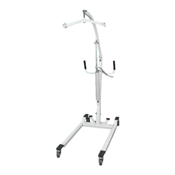
Page 2: Parts Description
HYDRAULIC PATIENT LIFT PARTS DESCRIPTION Lifting Arm Main Frame Hydraulic Pump Width Adjusting Pedal Castor Base Front Castor... -
Page 3: Hardware Included
MOB1068 HARDWARE INCLUDED • Hexagon bolt M10x75 x2 • Small Nut Cap x3 (I) • Hexagon bolt M10x60 (J) • Washer x2 (B) • Spacer x2 (K) • Lock Nut x2 (C) • Small Washer x3 (L) • Nut Cap x2 (D) •... - Page 4 ASSEMBLY INSTRUCTIONS Place the Main Frame Arm and align the holes with the Base. Fix (A) M10x75 hexagon bolt with (B) Washer and insert it through both the holes on the base. Attach the (C) nut and to the other end and tighten down using your wrenches.
- Page 5 MOB1068 2. Insert the Lifting Arm (G) into the upper groove of the frame. Make sure the holes are in alignment and then slip the Hexagon bolt M10x70 (F) with a Small Washer (L) through the hole. On the opposite side attach another Small Washer (L) and a Small Lock Nut (M).
- Page 6 4. Finish the Installation of the Hydraulic Pump (H) by attaching the top part to the Lifting Arm (G) by first lining up the holes. Insert a Small Washer (L) onto the Hexagon bolt M10x60 (J) then slide through the first hole. On the other side of the first hole be ready with a Spacer (K).
- Page 7 MOB1068 5. Insert (O) Sling Holder Pipe into the (N) Sling Holder. Attach this new piece to the Lifting Arm by aligning the holes on the Lifting Arm and the Sling Holder Pipe. Use the (P) Hexagon bolt M10x55 to secure the two together along with the Small Washer (L) and a Small Lock Nut (M).
- Page 8 Operate the hydraulic handle up and down to lift the patient. Slide the valve switch outwards (Away from the lift handle) and the hydraulic cylinder will decline, relying on the patient’s own weight. When it declines to a requested height, re-lock the valve switch.
- Page 9 MOB1068 Base Width Adjustment: The width of the base can be adjusted by pedal. Press on the left pedal for a wider base and the pedal on the right for a more narrow base. Lock and Unlock Rear Wheels: The rear wheels can be locked. Use your foot to lock and unlock the rear wheels.
-
Page 10: Care And Maintenance
OPERATION OF PATIENT LIFT Keep the lifting arm and patient’s body vertical. Make sure the operation of the lift is correct each time. WARNING: An imbalance during ascent increases the risk of tipping. Always use on flat grounds. Check and ensure the following items after finishing the assembling process: •... -
Page 11: Troubleshooting
MOB1068 TROUBLESHOOTING Patient Lift Doesn’t Work Check if there is any damage to the hydraulic cylinder. MAINTENANCE RECORD Date Fault Cause Remark... -
Page 12: Specifications
SPECIFICATIONS Device Name Hydraulic Patient Lift Model/type MOB1068 Product Size 47.25”×24.5” ×48.25” Fork Range 24.5” - 31.5” adjustable Lifting Range 31” (lowest), 68” (highest) Maximum Capacity 400 lbs. Net Weight 86 lbs. WARNINGS • Lift should only be operated by adults with proper knowledge of how to handle a lift and properly position a lift sling. - Page 13 MOB1068 • Always check the position of the sling and how it is pla- ced around your patient and placed on the four lift rings. Each sling has multiple height positions, make sure the height positions are all equal so your patient is balanced when being lifted.
Need help?
Do you have a question about the MOB1068 and is the answer not in the manual?
Questions and answers