Table of Contents
Advertisement
Quick Links
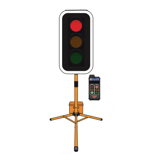
Optional Remote
This QuickStart Guide covers the PTL Controller
Operation as per Australian Standards AS- 4191:2015
and Various State Authority requirements.
For Advanced Features, download the Portable Traffic
Lights Advanced Features Document, this covers the
sections as follows:
1.
All-Red Time, Yellow and Green Manual
programming.
2.
Additional operational modes. These are not part
of the Australian Standards and may not apply to
specific state Type approvals.
3.
Additional features, Radio Link explained,
Fault logging as per Australian Standards,
troubleshooting guide.
This User Manual applies to Controllers operating on
firmware 07.01.xx or later.
THE PORTABLE TRAFFIC LIGHTS SHOULD ONLY BE OPERATED
BY QUALIFIED TRAFFIC MANAGERS.
PTL Compact Type 2 Operations
and Maintenance Manual
Controller QuickStart Guide
NxG
P T L C O M P A C T T Y P E 1 M A N U A L
PTL Controller
Showing optional
target board.
Target boards are
mandatory for NSW.
10:14am
4G
PTL PTLSG
EXIT
MASTER
SLAVE
STOP
STOP
GO
GO
DEMAND
Shut Down
SHUT DOWN
MENU
Optional
Remote
1
Advertisement
Table of Contents

Subscribe to Our Youtube Channel
Summary of Contents for Data Signs PTL Compact 2
- Page 1 PTL Compact Type 2 Operations and Maintenance Manual Controller QuickStart Guide Optional Remote PTL Controller This QuickStart Guide covers the PTL Controller Operation as per Australian Standards AS- 4191:2015 and Various State Authority requirements. For Advanced Features, download the Portable Traffic Lights Advanced Features Document, this covers the sections as follows: All-Red Time, Yellow and Green Manual...
-
Page 2: Contents Ptl Compact Type
Installation - Setting Up for Operation Step 1: Step 6: Fit Battery Box. Step 2: Step 7: Take out the stand. Twist and fit around the post. Step 3: Step 8: Loosen locking tab, Lock the holding lift the post to the bracket with a pin-hole &... - Page 3 Step 11: Step 16: Lift the flap and Switch on power plug the cable in as using switch as shown. shown. Connect the aerial cable. Step 12: Refer to Manual to use the PTL Remote. Completed setup. Step 13: To open control / battery box slide the locking pin underneath to the...
- Page 4 Installation - Target Board Setup (if optioned) Step 1: Remove the four sides from the side pocket. Step 2: Assemble this way. Step 3: Attach top section to the 2 sides. Line up the tick marks. Step 4: Place the assembled sections over the lamps as shown...
-
Page 5: Table Of Contents
Contents PTL Compact Type 2 Turning the Lights On QUICK START Controller display screens for Master and Slave Shuttle Control – Single-Lane Usage Plant-Crossing Control – 2 way Traffic Yellow Flash mode Setting All-Red, Yellow & Green Times Auto-Return Functions Other Menu Items for Basic PTL Operation Optional Remote P T L C O M P A C T T Y P E 1 M A N U A L... -
Page 6: Turning The Lights On
CLEAR ENTER ON / OFF Yellow aspects and progress to © 2022. Designed & manufactured by Data Signs Pty. Ltd. www.datasigns.com.au LAB 0014AB Issue 4. showing RED aspects. Also, the Controllers will complete a self-diagnosis and check any connected external equipment such as the optional vehicle detectors. -
Page 7: Quick Start
QUICK START M A I N M E N U [ A U T O ] V I E W P T L S T A T U S Q U I C K S T A R T U N I T S E T T I N G S The Quick Start Menu item is used to get your PTL Lights set up in a few simple steps: After selecting the Quick Start Menu, select... -
Page 8: Controller Display Screens For Master And Slave
Controller Display Screens for Master and Slave Master ID=0 The following values will be shown on the display panel during normal operation 1 2 . 1 V G S M : N / A 1 2 . 4 V A U T O - T I M E D S H U T T L E : 2 G R E E N C H A N N E L : 1... -
Page 9: Shuttle Control - Single-Lane Usage
SHUTTLE CONTROL These illustrations are intended to outline the different modes which can be used with Data Signs Portable Traffic Lights and should not be used as examples or guidelines on how to setup a roadwork site − Separate documentation is available for these purposes. Copyright © 2021 Data Signs Pty Ltd. All rights reserved.3 Each PTL unit will go to the Green signal phase in turn, with the All Red sequence in between each green phase. - Page 10 SHUTTLE: MANUAL MODE. Buttons used: MASTER: STOP or GO Manual mode is used when an operator wants to control the traffic. On start-up, both the Master and Slave will rest on All-Red phase until a demand for Green phase is entered. To enter a demand for either Red or Green phase, press the STOP or GO buttons.
- Page 11 SHUTTLE: AUTO MODE IT IS EXTREMELY IMPORTANT THAT THE ALL-RED INTERVAL IS SET CORRECTLY FOR EACH TRAFFIC CONTROL SITUATION. Buttons available for HOLD-RED/RESUME feature: In AUTO mode, the Portable Traffic Lights MASTER: STOP or GO will operate in cyclic order according to the pre-set times.
-
Page 12: Plant-Crossing Control - 2 Way Traffic
Both units show the same signal phase. These illustrations are intended to outline the different modes which can be used with Data Signs Portable Traffic Lights and should not be used as examples or guidelines on how to setup a roadwork site −... - Page 13 PLANT CROSSING: MANUAL MODE. Buttons used: MASTER: STOP or GO On start-up, both the Master and Slave will rest on Green signal phase for Plant-Crossing Control until a demand for Red signal is entered by the operator. The operator can enter a demand for All-Red signal using either the Master: STOP or Slave: STOP buttons.
-
Page 14: Yellow Flash Mode
PLANT CROSSING: AUTO MODE IT IS EXTREMELY IMPORTANT THAT THE ALL-RED INTERVAL IS SET CORRECTLY FOR EACH TRAFFIC CONTROL SITUATION. In AUTO mode, the Portable Traffic Lights will operate in cyclic order according to the pre- set times. AUTO mode allows plant vehicles to regularly cross over the road, or to turn onto the road. -
Page 15: Setting All-Red, Yellow & Green Times
Setting All-Red, Yellow & Green Times Normally the RED and GREEN TIMES ARE automatically calculated DURING QUICK START ALL-RED INTERVAL TIME Default time: 20 seconds. Range: 1 to 300 seconds. The All-Red interval is the period of time that the lights on both the Master and Slave units remain on the Red phase simultaneously. -
Page 16: Auto-Return Functions
For example; in hilly area or distances greater than what the RF link will provide. Note: All PTL controlled from DS-Live must be fitted with a Data Signs SIM card and be subscribed the the DS-Live platform. -
Page 17: Other Menu Items For Basic Ptl Operation
Other Menu Items for Basic PTL Operation While the Controller is in PROGRAM SELECT, use the buttons to navigate forward and back through the MENU’s to select all other programming functions. Press the button to exit the selected MENU and return to the main screen. Note: for more comprehensive information see the PTL Advanced Features Manual. - Page 18 Wireless Link Explained Each Traffic Light is fitted with an aerial located on the top of the lights. This will provide Wireless Radio communication between the PTL units; however, the units still need to be positioned in line-of-sight to each other. The maximum distance between the Master and Slave PTL's is about 500m, depending on surrounding environment.
- Page 19 Fault Conditions If any fault conditions occur as discussed throughout this document, the Portable Traffic Lights will go to Red. All critical faults are logged to a file on the SD card fitted to the Master Controller. The faults logged are outlined below. Reference back to the Australian Standard is provided in the table.
- Page 20 Master Controller is turned on, until the SD card is replaced. Note: the SD card must only be 2GB Max. To replace the SD Card purchase this from Data Signs, Parts online.
- Page 21 Glossary of Terms and Abbreviations Advanced Manual PTL-Compact Manual to assist with higer level set up and A Type-2 PTL Controller configuration, test processes. PTL-Stop-N-Go Aspects A simplified version of the PTL series of The actual lights or housing that contains products.
- Page 22 APPENDIX A Cycle and Phase Intervals for Shuttle and Plant Crossing Modes MASTER PHASE SHUTTLE OPERATION GREEN MASTER FLASHING BEACON MASTER SIGNAL DISPLAY RADIO LINK SLAVE SIGNAL DISPLAY SLAVE FLASHING BEACON GREEN SLAVE PHASE CYCLE GREEN PHASE PLANT CROSSING OPERATION GREEN MASTER FLASHING BEACON MASTER SIGNAL DISPLAY...
- Page 23 TSI-SP-062,049 and 50 where relevant AS4191-2015 Portable Traffic Signals. Suggestions & Improvements Data Signs develops its products with the end users in mind. As such, we are always open to suggestions for product improvement. Contact Data Signs, Head Office in Australia at: datasigns.com.au/help...
Need help?
Do you have a question about the PTL Compact 2 and is the answer not in the manual?
Questions and answers