Table of Contents
Advertisement
Advertisement
Chapters
Table of Contents

Related Manuals for Xilin CBD15W-LiX


Summary of Contents for Xilin CBD15W-LiX
- Page 1 OPERATION MANUAL & PARTS CATALOGUE CBD15W-LiX Pallet Truck with Lithium Battery...
- Page 2 WARNING W h e n u s i n g t h i s t r u c k , p l e a s e o b s e r v e t h e Only drivers who have received formal training or surroundings, do not distract.
-
Page 3: Table Of Contents
TABLE OF CONTENTS Truck Description 01/ DESCRIPTION Truck Parameters Truck Layout Assembly of handle Driving and Stopping Lifting and Lowering 02/ OPERATION Braking Emergency Reverse Safe Parking Routine Checks Electrical schematic diagram Adding hydraulic oil 03/ MAINTENANCE Truck hoisting Battery Charging and Replacing Trouble Shooting Packing list 04/ PARTS CATALOGUE... -
Page 4: 01/ Description
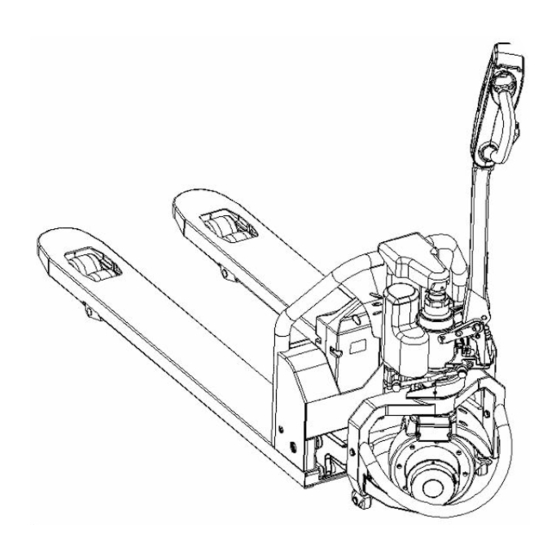
DESCRIPTION... - Page 5 01/ DESCRIPTION TRUCK DESCRIPTION Multi-function controller handle Lithium battery Tapered forktip Tandem PU rollers Driving wheel (OPTION)
- Page 6 01/ DESCRIPTION TRUCK PARAMETERS Model Name CBD15W-Li Manual Model Load Capacity 1500 kg Lowered Height 80 mm Forks Fork Length 1150/1220 mm Chassis Dimensions Overall Fork Widths 550/685 mm Maximum lifted height 190 mm Service Weight 135 kg Battery type lithium Battery Rated Voltage...
- Page 7 01/ DESCRIPTION TRUCK LAYOUT...
- Page 8 01/ DESCRIPTION HANDLE ASSEMBLY The handle has been removed before leaving the factory for the safe transportation and packaging, so the user has to install the handle before use, the installation steps are as follows Fig. 1 Fig. 2 2. Loose the screw 3, remove the cover 1.
- Page 9 01/ DESCRIPTION ASSEMBLY OF HANDLE Fig. 3 Fig. 5 Fig. 4 3. Insert handle assembly 5 (Fig. 2) into A (Fig. 1), connect handle assembly 5 to pump body 10 by pin 2. Thread the rod chain 8 through the hole of pin 2. Pull the handle to horizontal position, take out pin 9 and save it for next time use.
- Page 10 01/ DESCRIPTION ASSEMBLY OF HANDLE Fig. 6 Fig. 4 4. See Fig. 4&6, fix the screw and nut at the end of chain 8 into the groove of lever plate 11. 5. Pass the pin 2 through pin 2 and fix, install the cover plate 4 onto handle assembly 5.
-
Page 11: 02/ Operation
OPERATION... - Page 12 02/ OPERATION DRIVING AND STOPPING Plug in the battery connector. Turn on the key switch. Pull the handle to section B. A and C are breaking section. Rotate the accelerator to start the truck slowly (for safety, reason no abrupt acceleration). Return the accelerator to neutral position to stop the truck.
- Page 13 02/ OPERATION LIFTING AND LOWERING Lifting button Lowering lever Plug in the battery connector. Turn on the key switch. Press the lifting button on the handle to lift the forks. Pull the lever toward the operator to lower the forks.
-
Page 14: Braking
02/ OPERATION BRAKING Release the accelerator for normal Turn the handle to A or C quickly for braking, the truck stops slowly by the emergency braking, the brake will lock regenerative brake of the motor until the the wheel to achieve the emergency brake lock the wheels. -
Page 15: Emergency Reverse
02/ OPERATION EMERGENCY REVERSE Emergency reverse button THE EMERGENCY REVERSE BUTTON minimizes the possibility of the driver being pressed by the steering arm while driving the truck in slow speed. If the switch presses against the operator while the truck is driving toward the operator, the switch changes the direction of the truck. - Page 16 02/ OPERATION SAFE PARKING Release speed control button to stop the truck. Lower the fork to the lowest position. Turn off the key switch. Disconnect the battery connector if park for a long time.
- Page 17 MAINTENANCE...
-
Page 18: Routine Checks
03/ MAINTENANCE ROUTINE CHECKS Daily Maintenance : To keep the surface clean and examine if the power supply cable is damaged. Weekly Maintenance : To check the condition of the operational components, all fastening items, if oil leakage, if abnormal wearing in mechanical components exists, if abnormal temperature rises or sparks in electric equipment, etc. - Page 19 03/ MAINTENANCE ELECTRICAL SCHEMATIC DIAGRAM...
- Page 20 03/ MAINTENANCE ERROR CODE Code Description Possible causes and trouble shooting Feedback overspeed Controller fails, contact the manufacturer. Kernel running error Controller fails, contact the manufacturer. Speed sensor missing No speed feedback detected. To solve the problem as following: 1. Check the connection between speed sensor and controller; 2.
- Page 21 03/ MAINTENANCE ERROR CODE BUS charging fault Solve the problem as following: Check whether there is short circuit between u, V and W phases of motor. 2. Check whether the battery voltage supply is too low. 3. Check whether the drive coil is short circuited (do circuit and battery B -).
- Page 22 03/ MAINTENANCE ERROR CODE MACID detection failure The controller can network ID number is set repeatedly. Solve the problem by resting it. Main contactor drive failure The contactor inside the controller is abnormal. Power module failure Controller failure. Can node lost The controller is configured in parameter P1, and the interlock check is enabled in parameter P2Check.
-
Page 23: Adding Hydraulic Oil
03/ MAINTENANCE ADDING HYDRAULIC OIL Lifting and lowering the handle for two Find the oil filler Remove the screw at the oil filler with to three times after oil filling, then lift No.5 hexagon wrench, the oil volume is the fork to max. height and tighten the 250ml. - Page 24 03/ MAINTENANCE TRUCK HOISTING Fix and fasten the four hook positions according to the picture, then hoist the truck.
- Page 25 03/ MAINTENANCE BATTERY CHARGING AND REPLACING Turn off the key switch. Unplug the cable connector. Pull the battery grip upwardly. Remove the battery with a 45-degree angle to the ground.
-
Page 26: Battery Charging And Replacing
03/ MAINTENANCE BATTERY CHARGING AND REPLACING Keep the battery away from Working ambient temperature Charge and discharge the battery water or fire. of lithium battery is -10 ~ 45°C. every 3 months when storing for a long time. • Fully charge the battery before use. •... - Page 27 03/ MAINTENANCE BATTERY CHARGING AND REPLACING The lithium battery needs only Plug in the battery according to the With full charged battery, the 3 hours to achieve full charge. right positive and negative truck can work for 4 hours continuously. electrodes.
- Page 28 03/ MAINTENANCE BATTERY CHARGING AND REPLACING Li-ion charger • Must use the special Li-ion charger of our company; working voltage of charger 48V, maximum charging voltage 54.6V, charging current 6-7A. • Do not reversely charge the battery, check for the right positive and negative electrodes. •...
- Page 29 03/ MAINTENANCE TROUBLE SHOOTING Power Lamp Indicator Green lamp always on:70%-100% power Yellow lamp always on:40%-70% power Red lamp always on:10%-40% power Red lamp flashes:Nearly empty battery voltage • When the red lamp is on, it means low battery voltage, needs recharging. •...
-
Page 30: Trouble Shooting
03/ MAINTENANCE TROUBLE SHOOTING The table below provides some common failures of the truck in operation and the trouble shooting Faults Analysis of cause Trouble shooting Failed oil seal Replace the oil seal Slight damage or wear on the surface of one Hydraulic oil leakage Replace the damaged components or two components... -
Page 31: Packing List
03/ MAINTENANCE PACKING LIST Packing list of CBD15W-LiX Pallet truck with Lithium battery Consignee: Ex-work No.: Contract No.: Ex-work Date: Net weight Dimension Name Remarks (kg) (L×W×H) CBD15W-LiX pallet truck A complete set Technical documents, Accessory box accessories and spare parts. -
Page 32: Parts Catalogue
PARTS CATALOGUE... - Page 33 04/ PARTS CATALOGUE PARTS CATALOGUE General Assembly………………………………….……………………………….…30 Backrest Assembly…………………………………….………………………………32 Electric System…………………………………….……………………………………33 Handle Tiller……………………………………….…………………………………….35 Hydraulic System……………………………………………………..………………..37 Oil cylinder assembly…………………………………………………..…………..…38 Motor Pump……………………………………………………………………………...40 Steering Gear Assembly……………………………………………………………..41 Handle Assembly……………………………………………………………………….43 Driving Wheel Assembly…………………………………………………………….45 Connecting rod and rocker arm assembly……………………………….…47 Double Wheel System…………………………………………….…………………..49...
-
Page 34: General Assembly
04/ PARTS CATALOGUE PARTS CATALOGUE NOTE Electric Pallet Truck (CBD15W-LiX) General Assembly... - Page 35 04/ PARTS CATALOGUE PARTS CATALOGUE NOTE General Assembly Item No Drawing NO. Part NO. Name Q'ty Remarks CBD15W-LiX.01A-00 NULL Electrical system 053.02.0005.04 NULL Steering gear assembly CBD12W-Li.02-00 NULL Hydraulic system GB/T70.1 41100000037 Screw M6X12 ...
-
Page 36: Backrest Assembly
04/ PARTS CATALOGUE PARTS CATALOGUE NOTE Backrest Assembly Item No Drawing NO. Part NO. Name Q'ty Remarks GB/T70.1 41100000128 Screw M12X30 CBD12W-Li.22.01-00 30613000003 Backrest welding 30613000004 Backrest welding 001.05.0180.21 21703000101 040.01.0115.02 21605000020 Spring... -
Page 37: Electric System
04/ PARTS CATALOGUE PARTS CATALOGUE NOTE Electrical System... - Page 38 Screw M4X35 263.05.0000.43 20504000008 Line box 835.06.0003.03 20431000006 Wiring board CBD12W-Li.01.02-02 35401000024 Handle wiring harness CBD15W-LiX.01A.02-01 35401000203 Truck body wiring harness 835.05.0000.04 21006000011 Fixed buckle ACC-3-B 826.03.0000.06 21404000009 Puller GB/T818 41108000020 Screw M4X25 ...
-
Page 39: Handle Tiller
04/ PARTS CATALOGUE PARTS CATALOGUE NOTE Handle tiller... - Page 40 04/ PARTS CATALOGUE PARTS CATALOGUE NOTE Handle tiller Item No Drawing NO. Part NO. Name Q'ty Remarks 263.01.0000.07 20407000002 Horn button 263.01.0000.17 20404000001 Lifting button 263.99.0000.24 20418000021 Microswitch insert 740.99.0007.02 35612000017 Microswitch ...
-
Page 41: Hydraulic System
04/ PARTS CATALOGUE PARTS CATALOGUE NOTE Hydraulic System Item No Drawing NO. Part NO. Name Q'ty Remarks 490.03.1400.01 31001000128 Oil cylinder assembly CBD12W-Li.02.01B-00 30218000014 Motor pump 428.00.0012.01 20313000165 Joint JB/T982 44007000026 Washer 12 401.05.1282.01 31015000138 Oil inlet rigid pipe... -
Page 42: Oil Cylinder Assembly
04/ PARTS CATALOGUE PARTS CATALOGUE NOTE Oil Cylinder Assembly... - Page 43 04/ PARTS CATALOGUE PARTS CATALOGUE NOTE Oil Cylinder Assembly Item No Drawing NO. Part NO. Name Q'ty Remarks GB/T308 40002000017 Steel ball 3/4 505.01.0400.01 20304000231 Piston rod 506.09.0402.01 20307000024 Hood JB/T982 44007000005 Washer 10 ...
-
Page 44: Motor Pump
04/ PARTS CATALOGUE PARTS CATALOGUE NOTE Motor Pump Item No Drawing NO. Part NO. Name Q'ty Remarks CBD12W-Li.02.01B-01 21812000014 Connector 480.01.0008.01 30218000011 Pump GB/T70.1 41100000034 Screw M5X70 GB/T93 41300000003 Washer 5 701.48.0800.03 35205000031 DC motor... -
Page 45: Steering Gear Assembly
04/ PARTS CATALOGUE PARTS CATALOGUE NOTE Steering Gear Assembly... - Page 46 04/ PARTS CATALOGUE PARTS CATALOGUE NOTE Steering Gear Assembly Item No Drawing NO. Part NO. Name Q'ty Remarks 056.02.0107.05 30905000004 Handle assembly 001.01.0200.18 21702000052 GB/T879 41402000022 Pin 5X32 GB/T818 41108000014 Screw M4X10 ...
-
Page 47: Handle Assembly
04/ PARTS CATALOGUE PARTS CATALOGUE NOTE Handle Assembly... - Page 48 04/ PARTS CATALOGUE PARTS CATALOGUE NOTE Handle Assembly Item No Drawing NO. Part NO. Name Q'ty Remarks 056.02.0107.06 30909000003 Handle bar 234.02.0000.04 21405000004 Knob GB/T889.1 41208000002 Locknut M4 GB/T70.1 41100000005 Screw M4X8 ...
-
Page 49: Driving Wheel Assembly
04/ PARTS CATALOGUE PARTS CATALOGUE NOTE Driving Wheel Assembly... - Page 50 04/ PARTS CATALOGUE PARTS CATALOGUE NOTE Driving Wheel Assembly Item No Drawing NO. Part NO. Part name Q'ty Remarks GB/T 70.1 41100000043 Screw M6X20 GB/T93 41300000004 Washer 6 1115-220000-0B 90010000139 Driving wheel Z130BLD650-48A1-30S-00101 90030000071 Brushless motor ...
-
Page 51: Connecting Rod And Rocker Arm Assembly
04/ PARTS CATALOGUE PARTS CATALOGUE NOTE Connecting Rod and Wheel Carriage Assembly... - Page 52 04/ PARTS CATALOGUE PARTS CATALOGUE NOTE Connecting Rod and Wheel Carriage Assembly Item No Drawing NO. Part NO. Name Q'ty Remarks 143.10.0000.10 21106000021 Joint GB/T6173 41203000008 Nut M22X1.5 140.01.0101.11 31603000071 Connecting rod assembly 1150 31603000072 Connecting rod assembly 1220...
-
Page 53: Double Wheel System
04/ PARTS CATALOGUE PARTS CATALOGUE NOTE Double Wheel Assembly Item No Drawing NO. Part NO. Name Q'ty Remarks 012.01.0000.02 21221000009 Support plate GB/T276 43001000028 Bearing 6204-Z 001.01.0200.15 21702000049 GB/T879 41402000022 Pin 5X32 020.21.0080.02 21312000152 Wheel Q/NRY031 43101000006 Bearing ... - Page 54 NOTE...
Need help?
Do you have a question about the CBD15W-LiX and is the answer not in the manual?
Questions and answers
where can I get the wheels for this Pallet Jack parts 21312000162