Table of Contents
Advertisement
Quick Links
Advertisement
Table of Contents

Summary of Contents for J&R Technology JREX106
- Page 1 JREX106 Explosion Proof Analog Telephone Installation and User Guide...
- Page 2 J&R Technology Ltd...
-
Page 3: Table Of Contents
Content Foreword....................................1 1. General Operating Instructions............................1 2. Product Features...................................1 3. Technical Data..................................2 4. Overview of the Device..............................3-4 5. Display and Keyboard (Except for CB Version)......................5-6 6. Mode Switch (Except for CB Version)..........................6 7. CB Version Notes................................6 8. -
Page 4: Foreword
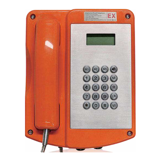
Foreword The JREX106 series telephones are designed to provide safe, reliable communication in hazardous areas. The housing is madeof impact and shock-resistant GRP and even resistant to acids, alkali and lubricants. Its robust design represents a perfect “packaging” for the latest requirements for Analog telephones combined with proven reliability for critical mission communications and high safety applications. -
Page 5: Technical Data
3. Technical Data Connection data Supply voltage 24 VDC to 65 VDC Supply current 20 mA DC to 100 mA DC Admissible frequency range 16...54Hz Maximum input short circuit current IK Ringer voltage 48 VAC to 90 VAC (calling frequency 21...54 Hz) Ringer impedance Greater than 6.0 kΩ... -
Page 6: Overview Of The Device
4. Overview of the Device Note: For CB version, the keypad and display are replaced by a solid metal plate. Outside View of the Telephone upper Part Inside View of the Telephone upper Part Note: The CB version is not equipped with a pin contact strip. - Page 7 Inside View of the Telephone lower Part Outside View of the Telephone lower Part Protection Class I – Components Factory supplied with: M20x1.5 threaded hole or a 1/2” NPT metal adapter for connecting armoured cables or conduit systems.
-
Page 8: Display And Keyboard (Except For Cb Version)
5. Display and Keyboard (Except for CB Version) 6. Mode Switch (Except for CB Version) Handset mode (except CB version) When picking up the handset, it’s in handset mode. Using the keys , you can adjust the handset volume for talking. If you wish to durably change the handset volume, use the menu "Settings / Handset volume". -
Page 9: Mode Switch (Except For Cb Version)
If the headset has been connected correctly, it takes the place of hands free talking. For this reason, hands-free talking with the headset is not possible. If you switch on the JREX106 with the key , you are operating in headset mode. If you lift the handset while in headset mode, the handset assumes a higher priority. -
Page 10: Explosion Protection - Device Description
• an intrinsically safe circuit with terminals within the telephone housing for the connection of an intrinsically safe loudspeaker. The accessories headset, second earpiece, external loudspeaker and external secondary ringer are not parts of the JREX106 telephone, but optional extras. - Page 11 Inside View of Telephone upper Part Inside View of Telephone lower Part Requirements for cables The line requires the use of cables larger than 0.5mm. The larger the diameter, the better the effect. It is best to connect the cable with a protective sleeve. Sling holder The holding strength for the handset is continuously adjustable.
-
Page 12: Connecting Plan
Upon disassembly of optional accessories, suited blind plugs must be used to close the resulting openings. Connecting a second ringer (bell-shunt) (optional accessory) Remove the sealing plug and tighten the M20x1.5 cable gland cap. Insert the wire of the second ringer and place it on the terminals in accordance with the connection diagram. -
Page 13: Mounting
11. Mounting Contents after unpacking Explosion proof telephone Operating instruction (optional) Explosion proof Horn and beacon (optional) Mounting screws and tamper screwdriver The telephone may be mounted hanging vertically on a wall or hanging vertically on a mounting plate. Wall Mounting Column Mounting... -
Page 14: Programmed Commands List
12. Programmed Commands List Commands Functions Commands Functions *#9999#11XXXX# Program the First speed dial number *#9999#19XXXX# Program the Ninth speed dial number (3 - 16 digits) (3 - 16 digits) *#9999#12XXXX# Program the Second speed dial number *#9999#10XXXX# Program the Tenth speed dial number (3 - 16 digits) (3 - 16 digits) *#9999#13XXXX#... - Page 15 Store a speed dial number E.g. Store a speed dial number “911” on button 5, 1 is the program parameter to store a speed dial number, the whole string is: *#1235#15911# Note: You can store speed dial numbers to 0~9 buttons, and just need change the button number after the program parameter. The speed dial number can be 3~14 digits.
-
Page 16: Information
Flash When the machine and one party call, need to transfer to a third party call press R key Redial Press the LR key to redial the last entered number M1-M3 M1, M2, M3 are for speed dialing number keys Heartbeat for Telephone Management With this function, you can store a service number to receive the “heartbeat calls”... - Page 17 Disposal The complete telephone should be disposed of as electronic waste. When the telephone is disassembled, plastics, metals and electronics components are to be disposed of separately. In every single case the national requirements and regulations for waste disposal must be observed. Warning and Security Instructions This telephone is an explosion proof and weatherproof telephone especially for use in a harsh industrial environment.
-
Page 18: Type Label
15. Type Label 16. CE Symbol We hereby declare this product is in compliance with the Essential Health and Safety Requirements of ATEX Directive 2014/34/EU, EMC Directive 2014/30/EU, Low Voltage Directive 2014/35/EU RoHS Directive 2011/65/EU and Waste of Electrical and Electronic Equipment WEEE Directive 2012/19/EC The appropriate standards, technical regulations and specifications you can take from the attached conformity declaration and the conformity declarations on our Website.
Need help?
Do you have a question about the JREX106 and is the answer not in the manual?
Questions and answers