
Summary of Contents for ProjectAir SC520
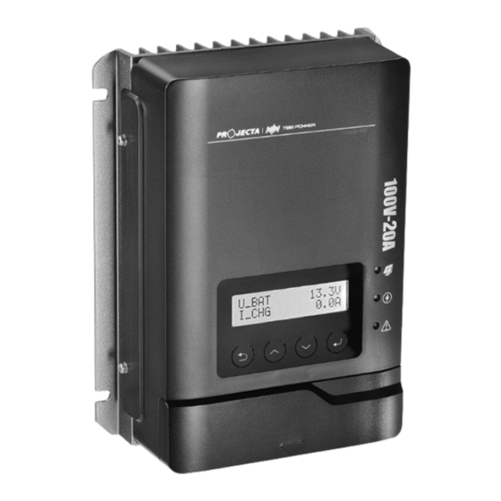
- Page 1 P/No. SC520, SC540 MPPT Solar Charge Controller 5 STAGE CHARGING 12/24/48V MULTI-CHEMISTRY SC520 SC540 Pictured: SC520...
-
Page 2: Safety Tips
• Keep instructions in a safe place for future reference. • Do not expose to rain, snow or liquids of any type, SC520 and SC540 are designed for indoor use only. • Beware of any nearby electrical equipment that may interfere with installing this device. -
Page 3: Product Features
2. Product Features • 5 Stage charging ensures the battery is charged to the optimum level. • Advanced MPPT technology to improve charging efficiency in different weather and temperature conditions. • Tempered glass screen with sturdy aluminium housing. • Selectable battery chemistry types, including AGM, GEL, WET and Lithium. •... -
Page 4: Device Diagram
3. Device Diagram Description Description LCD Display Screen RS485 Communication Port LED Indicator (PV, CHARGE, FAULT) Solar Input Terminals Cancel/Return Button Battery Terminals Increase/ Previous Button External Temperature Sensor Port 4 5 6 Decrease/ Next Button EPO Contacts Port Enter/ Select Button Output Dry Contacts Port Description Installation Mounting Holes... -
Page 5: Wiring Sequence
5. Wiring Sequence PV- - PV+ BAT- BAT+ TEMP Solar Panel SENSOR Fuse Ba�ery 1. Connect the positive battery wire followed by the negative battery wire. 2. Connect the positive solar array input wire followed by the negative solar array input wire (make sure your solar panels are fully covered to prevent electrical shock). -
Page 6: Pre-Operation Check
Step 1: Reconnect circuit breaker or fuse for the battery. Step 2: Reconnect circuit breaker or fuse for the PV array. Step 3: Set the parameters according to the setup wizard. Step 4: Observe the LED light to check if the SC520/SC540 is working normally. 6.3 Power OFF The SC520/SC540 will still contain residual power and heat after power OFF. -
Page 7: Charging Stages
6.5 Charging Stages The SC520/SC540 multi-staged algorithm is designed to charge the battery with high efficiency and reliability. Battery Voltage Charging Current Soft Start(Stage 1) – The controller will deliver ½ rated current until the battery voltage is over 11.5VDC or 10-minute time-out, then turn to the Bulk(Boost) Stage. Bulk(Boost) Charge (Stage 2A) – Utilising MPPT technology, the controller will deliver maximum rated current until batteries rise to absorption level. *Equalization Charge (Stage 2B) – Only applicable to Flooded,WET and AGM mode. Every 30 days, it will skip boost and automatically run equalization to rejuvenate the internal battery cells. Absorption Charge (Stage 3) – the controller will deliver constant voltage based on the battery chemistry setting until the charge current is less than 3A, then the controller will turn to float charge mode. Float Charge (Stage 4) – Only applicable to non-lithium batteries. When the battery is fully charged, it will reduce the voltage to float voltage setting as per chemistry select to keep the battery topped up. Recycle Charge (Stage 5) – After 10 days of Float charge, the controller will return to bulk charge and charge the battery to set voltage point. -
Page 8: Menu Introduction
>Para_Mode >Para_Ba�ery >Basic Set Alarm State: When errors >Change Password happen with >Advanced Set SC520/540, the >Setup Wizard alarm status will be >EQ Set displayed instead >Reset parameter ERROR: Failure, controller >Factory Set >Factory System stops charging >Factory Sample... - Page 9 7.1 Start-Up After power on, the LCD display will light up the backlight, show a boot animation and then display the following information in sequence. For SC520: PROJECTA SC520 For SC540: PROJECTA SC540 7.2 Real-Time Working Status After the initial startup, if the controller is working normally, the display will show the real-time device working status.
- Page 10 Default Interface Display Description Setting Range Setting Systen Module Parallal >Para System SYS_Module_Addr Address External Control 0 - Disable OutCtrl_CHG 0- Disable (Read Only) 1 - Enable Output dry contact 0 - Disable RlyCtrl_Config 0- Disable configuration 1 - Alarm Switch 0-Disable Silent_Mode_EN Silent Mode...
-
Page 11: Alarm Code
Automatic Page Turning 3~30s Time >Data & Time System Time Setting 8 Alarm Code The SC520/SC540 has two alarm levels: • Warning: the SC520/SC540 is still charging normally, but with warning alarm. MPPT WARN Example: U_BAT_LV • Fault: the SC520/SC540 has an error and charging stops. MPPT Err Example: PSU_LV 8.1 Alarm Code Chart... -
Page 12: Battery Temperature Sensor
Alarm Level Display Description Quick Troubleshooting Check and adjust the battery Buck_Short Cut Battery short circuit wiring Lower the maximum charging current setting The bulk stage charging current in the parameter setting I_Buck1_OC has exceeded the controller’s >Para_Battery maximum rating >Advanced Set >CHG_MAX_Current The controller has exceeded the... - Page 13 Controller Specifications Parameter Model No. SC520 SC540 System Wiring Negative Grounded Grounded Battery System 12/24/48VDC Voltage No-load Loss 1mA/12VDC, 3mA/24VDC. 5mA/48VDC Max Solar Input <100Voc <100Voc Voltage Rated Solar Charge Current 300W/12V 600W/12V Max Solar Input Power 600W/24V 1200W/12V 1200W/48V...
-
Page 14: Controller Dimensions
10. Controller Dimensions SC520 & SC540 Product Dimensions: 205 x 160 x 68.5mm Installation Area Dimensions: 160 x 150mm Installation Hole Size: 5 x 5mm... -
Page 15: Installation
4 x M5 mounting screw sets supplied. Please tighten the screws properly and make sure all 4 screws are installed to avoid falling. Install the SC520/SC540 as close to the batteries as possible. This will reduce the potential for voltage drop and ensure maximum performance of the equipment. - Page 16 WARRANTY STATEMENT Brown & Watson International Pty Ltd (“BWI”) of 1500 Ferntree Gully Road, Knoxfield, Vic., telephone (03) 9730 6000, fax (03) 9730 6050, warrants that all products described in its current catalogue will under normal use and service be free of failures in material and workmanship for a period of three (3) years from the date of the original purchase by the customer as marked on the invoice. This warranty does not cover ordinary wear and tear, abuse, alteration of products or damage caused by the purchaser. To make a warranty claim the consumer must deliver the product at their cost to the original place of purchase or to any other place which may be nominated by either BWI or the retailer from where the product was bought in order that the warranty...
Need help?
Do you have a question about the SC520 and is the answer not in the manual?
Questions and answers