
Related Manuals for BEA LPS-A6

Summary of Contents for BEA LPS-A6
- Page 1 INSTALLATION GUIDE INSTALLING THE LPS-A6 POWER SUPPLY MO- DULE IN THE EVERSOLO DMP-A6 / DMP-A6 MASTER EDITION...
- Page 2 Tools required: • LPS-A6 power supply kit • EverSolo DMP-A6 / DMP-A6 Master Edition • Phillips screwdriver • Allen key 2.0mm...
- Page 3 Step 1: Use a 2.0mm allen key to unscrew the 6 screws on the rear panel and the 7 screws on the underside of the unit. Total screws to remove: 13.
- Page 4 Step 2: Gently slide the device cover outwards about 20mm. Two webs connect the screen to the motherboard. Don’t use too much force.
- Page 5 Step 3: Lift and tilt the cover (gently). Caution: cables are attached to the cover, screen and motherboard. Do not undo them.
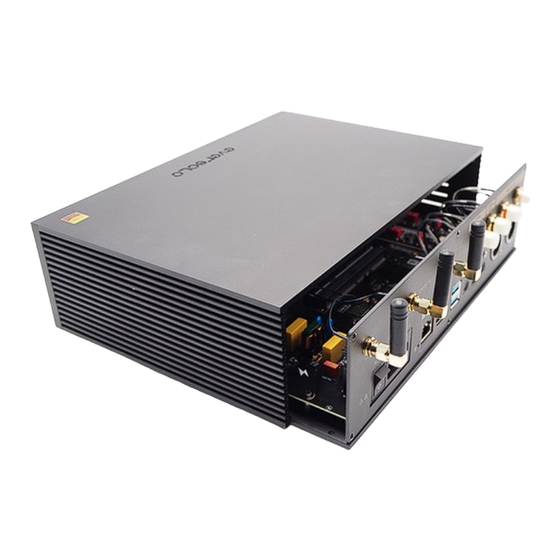
- Page 6 Step 4: Identify the switch mode power supply (SMPS) of the DMP-A6.
- Page 7 Step 5: Disconnect the jumper cable. This is a latched connector. Press the central part to unlock it, then pull it gently upwards.
- Page 8 Step 6: Use a Phillips screwdriver to remove the 6 screws securing the switching power supply.
- Page 9 Step 7: Remove the switching power supply module from the DMP-A6 and prepare the LPS-A6 module.
- Page 10 Step 8: Locate the insulation rings (4 pieces). Place them on the PCB spacers as shown in the following photos.
- Page 11 Step 9: Install the LPS-A6. Place it on the 4 isolation rings. Align the LPS-A6 correctly with the spacers. Note that the rings may move slightly. Use the 2.0mm allen key to align them.
- Page 12 Step 10: Use the existing screws to secure the LPS-A6 module to the chassis. Use a Phillips screwdriver to tighten the 4 screws. You’ll have a surplus of 2 screws. Keep them in a safe place.
- Page 13 Step 11: Install the silver-plated cable. Plug the connectors firmly into the sockets as shown in the following photos.
- Page 14 Step 12: Close and gently tilt the cover downwards. Remember that the cables are attached to the cover screen and to the motherboard. Do not disconnect them.
- Page 15 Step 13: Gently slide the cover inwards. Secure the cover to the rear and bottom panels. Use your 2.0mm allen key to tighten the 6 screws on the rear panel and the 7 screws on the underside of the unit.
Need help?
Do you have a question about the LPS-A6 and is the answer not in the manual?
Questions and answers