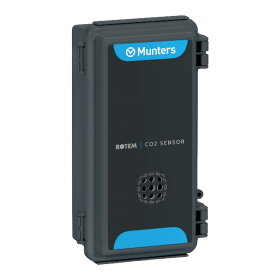
Summary of Contents for Munters CO2 Sensor
- Page 1 Sensor Installation Manual CO2 Sensor Ag/MIS/UmEn-2615-07/18 Rev 1.8 P/N: 116227...
- Page 2 Munters reserves the right to effect modifications to the apparatus in accordance with technical and legal developments.
-
Page 3: Table Of Contents
Platinum Wiring ....................3.2.2 Platinum Pro Wiring ....................................3.2.3 AC-2000 Plus Wiring 3.2.4 TRIO Wiring ......................Calibrating the Device..................13 Disconnecting the Sensor .................. 15 MAINTENANCE AND CARE ..........................................SPECIFICATIONS ......................TROUBLESHOOTING WARRANTY .......................... © Munters AB, 2020... -
Page 4: Introduction
Munters equipment. 1.3 Notes Date of release: May 2021 Munters cannot guarantee to inform users about the changes or to distribute new manuals to them. All rights reserved. No part of this manual may be reproduced in any manner whatsoever without the expressed written permission of Munters. -
Page 5: Introduction
The CO2 Sensor measures CO levels in an agricultural environment. Working in conjunction with a controller, the CO2 Sensor sends a signal when the measured CO levels fall outside the user-defined specifications. This signal activates the controller’s ventilation. Refer to Figure 1. -
Page 6: Operating Mode
2.2 Operating Mode The CO2 Sensor operates in a Current Loop mode (4 - 20 milliamps). In this mode, the CO 2 Sensor provides a signal proportional to CO 2 levels. Verify that J2 is not shorted (refer to Figure 2). -
Page 7: Installation
Disconnecting the Sensor • 3.1 Installing the Sensor NOTE The user needs to supply a 4-wired shielded cable that runs from the controller to the CO2 Sensor Connector. This cable is used to: • Connect the sensor to a power source •... - Page 8 Figure 7: Connector Numbers Table 1: Connecter Port Functions Port Number Function Wire Color (example) +12 V -12 V (COM) Black SIG Out White SIG COM Green NOTE The cable wiring used may have different colors. © Munters AB, 2020...
-
Page 9: Controller Connection
(Figure 9). Figure 9: Wired Unit in Protective Cover 3.2 Controller Connection Platinum Wiring • Platinum Pro Wiring • AC-2000 Plus Wiring • TRIO Wiring • Figure 10: CO2 Sensor Wiring Schematic (colors may vary) © Munters AB, 2020... -
Page 10: Platinum Wiring
Figure 11: Platinum Wiring Number Function Red wire: +12V Black wire: -12V (Sig COM) T5 or T6 port COM port Shield wire Power Supply Brown wire: phase Blue wire: neutral CAUTION Connect the shield to the safety ground! © Munters AB, 2020... -
Page 11: Platinum Pro Wiring
Figure 12: Platinum Pro Power Supply Wiring Number Function Red wire: +12V Black wire: -12V (Sig COM) IN 1 to IN 4 COM port Shield wire Power Supply Brown wire: phase Blue wire: neutral CAUTION Connect the shield to the safety ground. © Munters AB, 2020... -
Page 12: Ac-2000 Plus Wiring
1. Attach the other end of the sensor cable to the power supply and AC-2000 board (port 13 or 14). See Figure 13. 2. In Menu 94, map the CO2 sensor to the analog port to which the sensor is wired (2 or 3). -
Page 13: Trio Wiring
3.2.4 TRIO W IRING Figure 14: Trio- CO2 Sensor Wiring Number Function Red wire: +12V Black wire: -12V (Sig COM) S port COM port Shield wire Power Supply Brown wire: phase Blue wire: neutral CAUTION Connect the shield to the safety ground. -
Page 14: Calibrating The Device
The C02 sensor comes calibrated. In normal conditions fresh air should have approximately 350 - 450 ppm CO2. Calibrate the device if the following conditions are met: The CO2 sensor is exposed to fresh air or a room with open windows • The sensor reading is above 550. -
Page 15: Disconnecting The Sensor
NOTE If the device reading is still above 550 when exposed to fresh air, repeat the process. 3.4 Disconnecting the Sensor Before cleaning the poultry/animal house, disconnect the CO2 sensor. To disconnect the sensor: 1. Dismount the sensor from the wall. -
Page 16: Maintenance And Care
4 Maintenance and Care The CO2 Sensor requires little or no maintenance. The following are general maintenance rules: Avoid damaging the CO2 Sensor box. • Avoid contact with water or other fluids (when you clean the poultry house, • remove the box). -
Page 17: Troubleshooting
The field technician diagnostic LEDs are visual diagnostic indicators for the field technician only. They are not end-user serviceable parts or indicators. Table 3 details possible system failure issues. Table 2: CO2 Sensor System Failure Issues Problem Solution The Sensor Fail LED is lit when CO2 sensing Replace CO2 sensing element element fails. -
Page 18: Warranty
Munters plant was required: if this is not done, the user is fully responsible for the damage which they could suffer. - Page 19 Dismantling and assembly must be performed by qualified technicians and according to the manufacturer’s instructions. The use of non-original spare parts or incorrect assembly exonerates the manufacturer from all liability. Requests for technical assistance and spare parts can be made directly to the nearest Munters office. © Munters AB, 2020...


Need help?
Do you have a question about the CO2 Sensor and is the answer not in the manual?
Questions and answers