
Subscribe to Our Youtube Channel
Related Manuals for DeWalt DXPW3425E


Summary of Contents for DeWalt DXPW3425E
- Page 1 Instruction Manual Gas Pressure Washer If you have questions or comments, contact us. 1-877-362-4271...
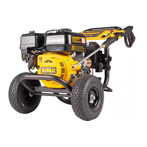
- Page 2 Fig. A Components Panel assembly Nozzle holder Professional spray gun Wheel Quick‑connect spray wand Frame Engine dipstick/oil plug Engine switch Starter grip Engine Choke control Fuel valve lever Gas cap Handle assembly High pressure hose High pressure pump Battery box Engine start connector Water sensing device nOTE: Photographs and line drawings used in this manual are for reference only and do not represent a specific...
- Page 3 Fig. B Fig. C Fig. D Fig. F Fig. E Fig. G Fig. I Fig. H Fig. J Fig. L Fig. M Fig. K...
- Page 4 Fig. N Fig. O Fig. P Fig. R Fig. Q Fig. S Fig. U Fig. T Fig. V Fig. X Fig. W Fig. Y...
- Page 5 Fig. Z Fig. AA Fig. BB...
- Page 6 QUICK SETUP GUIDE WARNING: To reduce the risk of injury, read the pressure washer instruction manual and the engine instruction manual before operating pressure washer. A install the handle Place handle onto frame, depress the snap buttons, and slide the handle assembly onto the frame until snap buttons snap into place.
- Page 7 BATTERY SET UP GUIDE 2 Connect the red wire to the 3 Close battery box 1 Open battery box. "+" (positive) terminal and the black wire to the "-" (negative) terminal. 5 Connect the bullet connector Complete battery 4 Connect the engine start to the engine start connector.
- Page 8 8 Place the fuel valve lever in the 9 Verify the Engine switch is 7 Release Air from system On position. turned to the On Position Release all air from pump and high pressure hose by depressing trigger until a steady stream of water is present.
-
Page 9: Important Safety Instructions
WARNING: Read all safety warnings and all for CO alarm before using. If you feel sick, instructions. Failure to follow the warnings and dizzy or weak at anytime, move to fresh air instructions may result in electric shock, fire and/or immediately. - Page 10 • Shorting the battery • Keep battery away from terminals together other metal objects like may cause burns or paper clips, coins, keys, DANGER: RISK OF EXPLOSION OR FIRE a fire. nails, screws, or other small metal objects that can WhAT CAn hAPPEn hOW TO PREVEnT iT make a connection from •...
- Page 11 • Your pressure • Direct spray away from self washer operates and others. at fluid pressures • Make sure hose and fittings and velocities high are tightened and in good DANGER: RISK OF UNSAFE OPERATION enough to penetrate condition. Never hold human and animal WhAT CAn hAPPEn hOW TO PREVEnT iT...
- Page 12 DANGER: RISK OF CHEMICAL BURN DANGER: RISK OF INJURY OR PROPERTY DAMAGE WHEN TRANSPORTING OR STORING WhAT CAn hAPPEn hOW TO PREVEnT iT WhAT CAn hAPPEn hOW TO PREVEnT iT • Use of acids, toxic or • Do not spray acids, •...
-
Page 13: Installation
WARNING: Risk of bursting. Use a tire pressure gauge to check the tires pressure before each use and while inflating tires; see the tire sidewall for the correct tire pressure. WARNING: RISK OF HOT SURFACES nOTE: Air tanks, compressors and similar equipment used WhAT CAn hAPPEn hOW TO PREVEnT iT to inflate tires can fill small tires similar to these very rapidly. - Page 14 NOTICE: DO NOT try to tum pressure regulator knob 2. Release quick‑connect coupler and twist nozzle to make past the built‑in stop or damage to the pump will result. sure it is secure in coupler. NOTICE: DO NOT overtighten the pressure control knob. WARNING: Flying object could cause risk of serious If overtightened the knob COULD break and result in injury.
- Page 15 • Operate pressure washer in a well‑ventilated area. Avoid enclosed areas such as garages, basements, etc. • Never operate unit in or near a location occupied NOTICE: Use of fuels with greater than 10% ethanol by humans or animals. are not approved for use in this product per EPA WARNING: Risk of fire, asphyxiation and burning.
-
Page 16: Maintenance
Engine 14. As the engine warms up, move the choke to the open position. Consult the engine instruction manual for the manufacturer's 15. Depress trigger on gun to start water flow. recommendations for any and all maintenance. WARNING: Do not allow the unit to run for nOTE: The pressure washer frame is equipped with an oil more than two minutes without the gun trigger drain hole to help make changing the engine oil easier. -
Page 17: Pressure Washer
‑ Disconnect the red wire from the battery’s positive 3. Turn the fuel valve to the OFF position. (+) terminal. 4. Continue to run the engine until it stops from the lack of 4. Remove the old battery and dispose of according to fuel in the carburetor fuel bowl. -
Page 18: Service Information
as short circuit may result. Keep away from children. warranty inspection. The judgments and decisions of the Failure to comply with these warnings could result in manufacturer concerning the validity of warranty claims fire and/or serious injury. are final. These warranties pass through to the end user and are To preserve natural resources, please recycle or dispose of batteries properly. -
Page 19: Troubleshooting Guide
Choke control: Opens and closes carburetor choke valve. • Normal wear of moving parts or components affected by moving parts. CU: Cleaning Units. GPM multiplied by psi. (GPM x PSI = CU) Engine and Emissions Control system Fuel valve lever: Opens/closes connection between fuel tank and carburetor. - Page 20 CODE POssiBlE CAUsE POSSIBLE SOLUTION Choke lever in the CHOKE position on a hot engine or an Move choke to the NO CHOKE po si tion. engine that has been exposed to thermal heat for a long period of time. Fuel valve CLOSED.
- Page 21 The FNA Group, Inc.,7152 99th Street Pleasant Prairie, WI 53158 (DEC20) Part No. 7114664 Copyright © 2020 The following are trademarks for one or more D WALT power tools: the yellow and black color scheme, the “D” shaped air intake grill, the array of pyramids on the handgrip, the kit box configuration, and the array of lozenge‑shaped humps on the surface of the tool.
Need help?
Do you have a question about the DXPW3425E and is the answer not in the manual?
Questions and answers