
Summary of Contents for JTS REMOSET SP T-IR
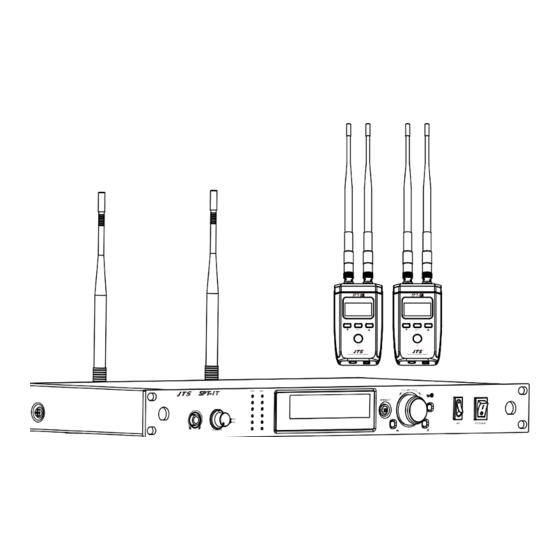
- Page 1 UHF PLLTrue D ivers ity Receiver UHF PLLTrue D ivers ity Receiver PUSH / CONTROL POWER E X I T SETUP VOLUME Instruction Manual UHF PLL 2.4G RF Wireless Synchronization Technology...
- Page 2 One year product warranty Equipment Product Model serial number Customer Contact name number Address Purchase date Selling store stamp Be sure to put store stamp and fill in purchase date for the warranty to be effective! Warranty description 1. Be sure to put the warranty label indicating purchase date on the bottom of equipment to ensure your interest in maintenance and service.
-
Page 3: Table Of Contents
Contents 1. Notes for system operations 2. Features 3. Specifications 3-1 UHF PLL True Diversity Receiver // 3-2 UHF PLL Transmitter // 4. Description of Parts 4-1 UHF PLL True Diversity Receiver // 4-2 UHF PLL Transmitter // 4-3 Accessories 5. -
Page 4: Notes For System Operations
36MHz line design, with a total of six groups 1441 frequency points that can be selected, and a built-in mode of non-interference frequency. • The SPT-1T transmitter combines JTS' patented 2.4GHz REMOSET wireless transmission technology with highly stable circuitry and signal performance, to synchronize frequency and channel settings to the SPT-1R receiver just by pressing a button. -
Page 5: Specifications
3. Specifications 3-1 UHF PLL True Diversity Receiver // Model Frequency Oscillation Phase-Locked Loop, PLL Carrier Frequency 470~608MHz Number of Channels 2 Channels Frequency Matching 2.4GHz RF Antenna Selection True Diversity Signal to Noise Ratio (S/N) >106dB(A) Total Harmonic Distortion (T.H.D) <0.5%@1KHz Reception Sensitivity -95dBm , S/N>80dB... -
Page 6: Uhf Pll Transmitter
3-2 UHF PLL Transmitter // Model Frequency Oscillation Phase-Locked Loop, PLL 470~608MHz Carrier Frequency Frequency Matching 2.4GHz RF RF Power Output 10mW/50mW (according to local regulations) <±10KHz @ Fc RF Stability Modulation Frequency ±48KHz Deviation Spurious Emissions <-50dBc LCD Display Group, Channel, Frequency, Mute, Remoset ID, Volume Controls Power, Group, Channel, Frequency, Transmitted Power, Key Lock... -
Page 7: Description Of Parts
4. Description of Parts 4-1 UHF PLL True Diversity Receiver // Power Switch : Press once to turn on; press and hold for two seconds to turn off. LCD Display : Displays the emitter setting parameters. Antenna : Receiver Antenna Audio Output Connector : 3P Mini XLR connector. - Page 8 LCD Display indicates the transmitter channel that Transmitter Channel Indication: corresponds to the transmitter via the frequency matching function User's Name Key Lock Receiver Antenna Indication 1: ANT1 2: ANT2 : No signal RF Reception Strength Indication Audio Indication The Current Default Group Channel The Current Frequency Remoset ID Remoset ID2...
-
Page 9: Uhf Pll Transmitter
4-2 UHF PLL Transmitter // 9 10 Front PUSH / CONTROL SETUP E XIT Rear ANTENNA OUT ANTENNA OUT POWER Made in Taiwan Power ON/OFF : refers to power "ON". refers to power "OFF ". RF Switch : Enables/disables the RF signal. Key Lock : Press and hold for 2 seconds to lock all key functions. - Page 10 CH1 Volume Indication CH2 Volume Indication Ø 6.3 mm Stereo Headphone Jack Volume Control/Monitoring Channel Indication: Rotate: monitoring volume adjustment Press: switching channels CH1, CH2 on together: listen to both channels at the same time CH1 on: listen to CH1 only CH2 on: listen to CH2 only AC Power Jack: 100~240VAC CH.2 BNC Antenna Output Jack...
- Page 11 LCD Display Content Setup Screen Transmitting Channel Indication User's Name Key Lock Stereo/Mono Status Indication : Stereo : Mono Transmitted Power Status Indication : High transmitting power : Low transmitting power RF Emission Status Indication : RF signals emission on : RF signals emission off Remoset ID Volume...
-
Page 12: Accessories
4-3 Accessories AC Power Cable (SPT-1T Accessory) Switching Power Transformer (SPT-1R Accessory) ∅ 3.5mm X 50cm Cable (mini XLR female to XLR male/SPT-1R Accessory) Velcro, Mount, Screws (SPT-1R Accessory) Transparent Waterproof Cover (SPT-1R Accessory) -
Page 13: Connecting
5. Connecting 5-1 UHF PLL True Diversity connection and installation // 1. Connecting to the power supply Connect to the power adapter: Plug the receiver into the DC socket first, and then plug the other end into the AC socket (100~240VAC). 2. - Page 14 There are two ways to mount receivers to active speakers concerning as stated in the content below: I. Method 1 (speaker with screws): 1. Turn out the screws on the side of the active speaker, lock the attached mount and screws into the screw holes of the speaker (Figure 1). 2.
-
Page 15: Uhf Pll Transmitter
5-2 UHF PLL Transmitter Installation // 1. Connecting to the power supply Connect to the AC power cable: Plug the transmitter into the AC outlet first, and then plug the other end into the AC outlet (100~240VAC). 2. Connecting to the audio signal cable Audio cable: XLR or Ø6.3mm audio cable, one end connects the audio source to the “SPT-1T OUTPUT BALANCED”... -
Page 16: Instructions For Use
6. Instructions for use 6-1 How to use // Parameter Settings Press the SET button for 2 seconds to enter the setting mode; press the ▲/▼ button to select the item, and press SET again to enter the setting mode. Meanwhile, you can press▲/▼... - Page 17 (2) ID ID of SPT-1T and SPT-1R should be the same to complete pairing. (3) ID2 Please refer to the "Remoset" section of the instruction manual. (P.19) (4) Save and Exit Save the settings and return to the main menu. (5) Exit without Save Return to the main menu without saving the setting.
- Page 18 10. Factory Reset Restore factory settings Cancellation 6-2 How to use // Press the SETUP key for 2 seconds to enter the setting mode. Use the rotary to select the item, click the rotary switch (or press the SETUP key) to enter switch the setting screen, rotate the rotary switch to adjust the desired value or function,...
- Page 19 (3) Volume Adjustment range: -20dB ~ +20dB The graph currently sets the sensitivity to Gain 0dB (default) (4) Remoset ID Remoset ID: 0~255. This setting affects the usage of REMOSET; The remoset ID settings of the receiver and transmitter must be the same to enable the REMOSET. (5) Remoset Config SPT-1T can set up 5 different audio delay times to synchronize to 5 receivers with...
- Page 20 (6) User Name Rotate the shuttle to select a letter, number or symbol, then click the shuttle to fill in and set the next word. 3. User Group (1) Edit G: U1~U6 , CH : 1~24 Frequency: When displayed as ------ MHz, this channel is not enabled.
- Page 21 6. System Options (1) Screen Contrast : 0~9 (default 5) (2) Screen Brightness: 0~9 (default 5) (3) Indicator Brightness: 0~9 (default 5) (4) Language 1.English 2.中文 (5) Factory Reset Restore to factory settings Cancellation...
- Page 22 Remoset REMOSET : Press the REMOSET button and the blue light will start flashing, indicating that the frequency data is being transmitted. REMOSET success: The receiver screen flashes three times. REMOSET failure: If the receiver does not respond, please check: (1) Whether the "frequency range label"...
-
Page 23: Notes For The Product
7. Notes for the product (1) To achieve the best reception of the signals, keep the receiver at least 3 meters apart from the transmitter. (2) Keep a distance of at least 50 cm between the receiver, the transmitter and other metal objects. IMPORTANT NOTE The changes or modifications not expressly approved by the party responsible for compliance could void the user’s authority to operate the equipment. - Page 24 59508-132-02...
Need help?
Do you have a question about the REMOSET SP T-IR and is the answer not in the manual?
Questions and answers