Sony XC-HR50 Operating Instructions
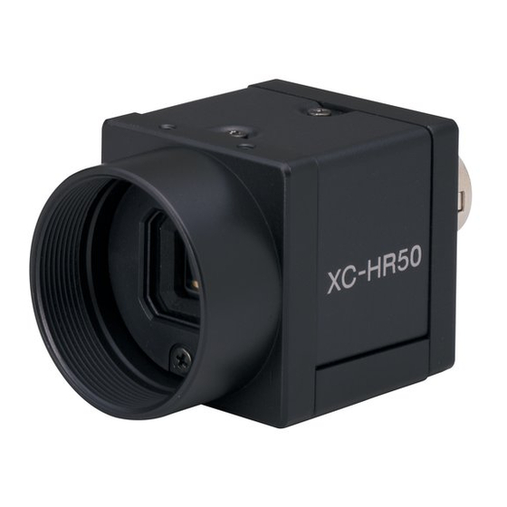
Black-and-white video camera module
Hide thumbs
Also See for XC-HR50:
- Technical manual (33 pages) ,
- Specifications (4 pages) ,
- Brochure (4 pages)
Advertisement
Quick Links
3-206-742-01 (1)
Black-and-White
Video Camera Module
取扱説明書
Operating Instructions
お買い上げいただきありがとうございます。
電気製品は、安全のための注意事項を守らないと、けがをし
たり周辺の物品に損害を与えることがあります。
この取扱説明書には、事故を防ぐための重要な注意事項と製品の取り扱い
かたを示してあります。この取扱説明書をよくお読みのうえ、製品を安全
にお使いください。お読みになったあとは、いつでも見られるところに必
ず保管してください。
XC-HR50
Sony Corporation 2002
Printed in Japan
安全のために
ソニー製品は安全に充分に配慮して設計されています。しかし、まちがった
使いかたをすると、火災や感電などにより死亡や大けがなど人身事故につな
がることがあり、危険です。
事故を防ぐために次のことを必ずお守りください。
• 安全のための注意事項を守る。
• 長期間、安全にお使いいただくために、定期点検をすることをおすすめ
します。点検の内容や費用については、お買い上げ店にご相談ください。
• 故障したら使わずに、お買い上げ店にご連絡ください。
警告表示の意味
行為を禁止する記号
この取扱説明書および製品では、 次のよ
うな表示をしています。 表示の内容をよ
く理解してから本文をお読みください。
行為を指示する記号
火災
この表示の注意事項を守らないと、
けが
やその他の事故により
をしたり周
損害
辺の物品に
を与えたりすることが
あります。
けが
下記の注意事項を守らないと、
をしたり周辺の物品に
を与えることがあります。
内部に水や異物を入れない
水や異物が入ると、火災の原因となります。
万一、水や異物が入ったときは、 すぐに本機が接続され
D C
ている電源供給機器の電源を切り、
電源ケーブルや
接続ケーブルを抜いて、お買い上げ店にご相談くださ
い。
分解しない、 改造しない
分解や改造をすると、 火災やけがの原因となります。
点検および修理は、お買い上げ店にご依頼ください。
カメラケーブルを傷つけない
カメラケーブルを傷つけると、火災や故障の原因となる
ことがあります。次の項目をお守りください。
• 設置時に、 製品と壁やラック、 棚などの間に、 はさみ込
まない。
• カメラケーブルを加工したり、傷つけたりしない。
• 重いものをのせたり、 引っ張ったりしない。
• 熱器具に近づけたり、 加熱したりしない。
• カメラケーブルを抜くときは、必ずプラグを持って抜
く。
芯線の露出や断線などでカメラケーブルが傷んだら、お
買い上げ店に交換をご依頼ください。そのまま使用する
と、火災の原因となります。
設置は確実に
設置については、必ずお買い上げ店にご相談ください。
壁面や天井などへの設置は、本機と取り付け金具を含む
重量に充分耐えられる強度があることをお確かめくだ
さい。 充分な強度がないと、 落下して、 大けがの原因とな
ります。
1
1
また、
年に
度は、 取り付けがゆるんでいないことを点
検してください。
指定された電源を使う
この取扱説明書に記されている電源供給機器 (カメラア
ダプターなど) でお使いください。規定外の電源でのご
使用は、 火災の原因となることがあります。
指定されたカメラケーブル、 接続ケーブルを使う
この取扱説明書に記されているカメラケーブル、接続
ケーブルを使わないと、 火災や故障の原因となることが
あります。
Owner's Record
The model and serial numbers are located on the bottom.
Record the serial number in the space provided below.
Refer to these numbers whenever you call upon your Sony
dealer regarding this product.
Model No. XC-HR50
Serial No. ______________
Important Safety Instructions
• Read these instructions.
• Keep these instructions.
• Heed all warnings.
• Follow all instructions.
• Do not use this apparatus near water.
• Clean only with dry cloth.
• Do not block any ventilation openings.
Install in accordance with the manufacturer's instructions.
• Do not install near any heat sources such as radiators,
heat registers, stoves, or other apparatus (including
amplifiers) that produce heat.
• Only use attachments/accessories specified by the
manufacturer.
• Unplug this apparatus during lightning storms or when
unused for long periods of time.
• Refer all servicing to qualified service personnel.
Servicing is required when the apparatus has been
damaged in any way, such as power-supply cord or plug is
damaged, liquid has been spilled or objects have fallen into
the apparatus, the apparatus has been exposed to rain or
moisture, does not operate normally, or has been dropped.
WARNING
To prevent fire or shock hazard, do not expose
the unit to rain or moisture.
For the customers in the USA
This equipment has been tested and found to comply with the limits for
a Class A digital device, pursuant to Part 15 of the FCC Rules. These
limits are designed to provide reasonable protection against harmful
interference when the equipment is operated in a commercial
environment. This equipment generates, uses, and can radiate radio
frequency energy and, if not installed and used in accordance with the
instruction manual, may cause harmful interference to radio
communications. Operation of this equipment in a residential area is
likely to cause harmful interference in which case the user will be
required to correct the interference at his own expense.
You are cautioned that any changes or modifications not expressly
approved in this manual could void your authority to operate this
equipment.
The shielded interface cable recommended in this manual must be
used with this equipment in order to comply with the limits for a
digital device pursuant to Subpart B of Part 15 of FCC Rules.
This device complies with Part 15 of the FCC Rules. Operation is
subject to the following two conditions: (1) This device may not
cause harmful interference, and (2) this device must accept any
interference received, including interference that may cause
undesired operation.
For customers in Canada
This Class A digital apparatus complies with Canadian ICES-003.
Pour les utilisateurs au Canada
Cet appareil numérique de la classe A est conforme à la norme
NMB-003 du Canada.
A
カメラ
/
Camera
損害
2
GND2
3
GND3
B
1
2
4
3
C
1
3
4
2
3
DC-700
WEN
HD
VIDEO
CAMERA
AC IN
1
1
2
2
TRIG
VD/SYNC
6
5
7
8
9
6
D
1
2
2
3
4
日本語
日本語
日本語
日本語
日本語
カメラ設置上のご注意
カメラ設置の際は、周辺機器を含めてカメラに接続されている各機器間で接
地電位の差が生じないようにしてください。接地電位差により故障の原因と
なる場合があります。設置の都合により電位差を生ずる場合は、機器の内い
ずれかひとつの機器だけを接地するようにしてください。
1 電源
3 接地電位差
使用上のご注意
電源について
DC+12V
で動作します。リップル、ノイズのない安定した電源をお使いくだ
さい。
使用・保管場所
次のような場所での使用および保管はお避けください。
• 極端に暑い所や寒い所。適正使用温度は
• 激しい振動のある所。
• 強力な電波を発生するテレビ、ラジオの送信所の近く。
お手入れ
レンズや光学フィルターの表面に付着したごみやほこりは、ブロアーで払っ
てください。外装の汚れは、乾いた柔らかい布でふきとります。ひどい汚れ
は、中性洗剤溶液を少し含ませた布でふきとった後、からぶきします。アル
コール、ベンジンなどは、変質したり塗料がはげることがありますので、使
用しないでください。
概要
XC-HR50
は固体撮像素子
白黒ビデオカメラモジュールです。
高画質
VGA
33
CCD
対応の
万画素
かな画像を再現します。また正方画素
ペクト比変換は不要です。
多様なモード設定
リアパネルのスイッチの切り換えにより、以下のモード設定が可能です。
• ゲイン
:
固定/手動調整
:
• 読み出しモード
ノーマル(
• ハイレートスキャン機能
• 同期入出力
75
•
Ω終端
• シャッター機能
:
ノーマル/トリガーシャッター
• シャッタースピード
外部同期
HD
、
VD
信号:入力された
て外部同期で動作します。
内部同期信号出力
HD
信号と
VD
信号は、リアパネルのスイッチを変更することにより、
コネクターから出力させることができます。
電子シャッター
F L
(フリッカーレス)モードと豊富なシャッタースピード(
1/30000
秒)の中から、撮影条件に合った速度が選べます。
外部トリガーシャッター機能(
トリガーを入力することにより、
物体を正確にとらえます。
ハイレートスキャン機能
有効な映像出力ライン数を限定することにより、高速な画像処理に適したフ
レームレートの高い映像出力が得られます。
ビニング機能
1
2
垂直方向の
画素を混合した映像信号が
ド比で感度がほぼ2倍となります。
GND1
筐体固定
筐体固定用のネジ穴が
CCD
あります。ここでカメラモジュールを固定すれば、光軸のずれを最小限にと
どめることができます。
4
3
EIAJ12
新
ピンコネクターピンアサイメント準拠
トリガーパルスや
WEN
信号を追加した、新しいピン配置になっています。
構成
白黒ビデオカメラモジュール
は、次のとおりです。(いずれも別売りです。
1 白黒ビデオカメラモジュール
CCD
を用いた、小型、高解像度の白黒カメラです。
2 カメラケーブル
CCXC-12P02N
25N
(
25m)
カメラモジュール裏面の
号の送出、同期信号の授受を行います。
5
C
マウントレンズ
3
推奨レンズ:
VCL-08YM/12YM/16Y-M/25Y-M/50Y-M
DC-700
4 カメラアダプター
AC
電源から電力を供給する場合に、カメラモジュールに接続して使用しま
す。映像信号の送出および同期信号の授受も行えます。
5 三脚アダプター
VCT-333I
三脚を使ってカメラモジュールを固定するとき、このアダプターをカメラモ
ジュールの底部に取り付けます。
XC-HR50
1
接続例
2
DC-700
(別売)との接続例
カメラモジュールを、カメラアダプター
4
す。カメラアダプター
DC-700
ご覧ください。
5
1 モニター
C
VCL-16Y-M
2
マウントレンズ(
75
3
Ω同軸ケーブル
CCXC-12P05N
4 カメラケーブル(
TRIG
5
発生器、画像処理装置
6 同期信号発生器
各部の名称と働き
前面/上面/底面
1 レンズマウント(
C
マウント
C
マウント式のレンズや光学機器を取り付けます。
1
ご注意
C
マウント式のレンズとして、レンズマウント面からの飛び出し量が
以下のものを使用してください。
1 レンズマウント部
2 カメラ固定用基準穴(上面)
3 カメラ固定用基準穴/三脚取り付け用ネジ穴(底面)
4 カメラ固定用基準穴(底面)
カメラモジュール固定用に高い精度で切られたネジ穴です。ここでカメラモ
ジュールを固定すると、光軸のずれを最小限にとどめることができます。
◆ 詳細はユーザーズガイドをご覧ください。
4
つのカメラ固定用基準穴は三脚アダプター取り付け用ネジ穴としても
3の
使用できます。三脚を使うときは、この
VCT-333I
を取り付けます。
English
図
A
When installing the camera
When you install the camera with various peripheral devices and if the
devices have different ground electric potential, ground only one device. In
case there is an ground electric potential difference, the camera may be
damaged.
1 Power supply unit
2 異常電流
3 Ground electric potencial difference
4 モニター
Notes on Operation
Power supply
The camera operates on +12V DC. Use a stable power source free from
ripple or noise.
Foreign bodies
Be careful not to spill liquids, or drop any flammable or metal objects in the
camera body.
Locations for operation and storage
0
〜
40
℃です。
Avoid operation or storage in the following places.
• Extremely hot or cold locations. Recommended temperature range is 0°C
to 40°C. (32°F to 104°F)
• Locations subject to strong vibration
• Near generators of strong electromagnetic radiation such as TV or radio
transmitters.
Care
Use a blower to remove dust from the surface of the lens or optical filter.
Clean the exterior with a soft, dry cloth.
If the camera is very grimy, apply a cloth soaked in a mild detergent then
wipe with a dry cloth. Do not apply organic solvents such as alcohol or
benzine which may damage the finish.
Overview
CCD
(
Charge Coupled Device
)を採用した
Before operating the unit, please read this manual thoroughly and retain for
future reference.
The XC-HR50 is a monochrome video camera module using a progressive
VGA
648
494
により、
相当(
×
画素)のきめ細
scan CCD (Charge Coupled Device) solid state image sensor.
CCD
の採用により、画像処理時のアス
High image quality
The progressive scan CCD (330,000 dots, VGA compliant) provides a high-
resolution image with 648 × 494 pixels. By adopting square pixels, images
can be processed using the original aspect ratio without a converting
procedure.
Various mode settings
60 fps
120 fps
)/ビニング(
)
Rear panel switches allow the following mode settings.
• Gain: Fix/Manual
• Read mode: normal (60 fps)/binning (120 fps)
• High rate scan
• Synchronized input/output
• 75Ω termination
• Shutter: Normal/Trigger shutter
• Shutter speed
HD
、
VD
信号を自動的に識別し、その信号に応じ
External synchronization
HD (horizontal drive), VD (vertical drive) signals: The camera module
12
ピン
Internal sync signal output
You can output the HD and VD signals from the 12-pin connector by
changing the rear panel switch.
Electronic shutter function
1 / 1 2 5
〜
Shutter speed can be selected from a wide range (1/125 to 1/30000 sec.) or
in flickerless (FL) mode.
1/4
〜
1/100000
秒)
External trigger shutter function (1/4 to 1/100000 sec.)
1
枚の静止画が得られます。高速で移動する
You can obtain a freeze picture by inputting an external trigger. This
function is useful to shoot a fast-moving object clearly.
High rate scan
The camera module can limit the number of effective video output lines to
achieve high frame rates, enabling high-speed image processing.
Binning
By "binning" two pixels that align vertically, you can acquire sensitivity twice
as high as that in the normal mode, and a frame rate of 120 fps.
120 fps
で得られます。ノーマルモー
Body fixing
The screw holes to install the camera module are located under the front
panel (the CCD reference plane). Installing the camera module on the front
の基準面が含まれているフロントパネルの下部に
panel minimizes deviation of the optical axis.
The connector complies with the new EIAJ 12-pin
assignment
The new pin arrangement allows the connector to accept a trigger pulse and
a WEN signal.
System Components
図
B
XC-HR50
を中心としたシステムの構成品目
The Black-and-White Video Camera Module XC-HR50 system comprises
the following optional products (available separately).
)
1 Black-and-White Video Camera Module
This is a small-size, high-resolution, monochrome video camera module
using a progressive scan CCD image sensor.
(
2m
)
/05N
(
5m
)
/10N
(
10m
)
/
2 CCXC-12P02N (2m, 6.6ft)/05N (5m, 16.4ft)/10N (10m, 32.8ft)/25N
DC IN/SYNC
This is attached to the DC IN/SYNC connector of the camera module and is
端子に接続し、電力の供給や映像信
used for power supply, transmission of video signals, and exchange of sync
signals.
3 C-mount lens
Recommended lens: VCL-08YM/12YM/16Y-M/25Y-M/50Y-M
4 DC-700/700CE camera adaptor
This is connected to the camera module to enable power supply from
ordinary AC power source, and also handles transmission of video signals
from the camera module and exchange of sync signals between the camera
module and an external sync signal generator.
5 VCT-333I tripod adaptor
This attaches to the bottom of the camera module to fix the camera module
to a tripod.
C
図
Connection example
DC-700
を介して電源に接続しま
Connecting DC-700/700CE (not supplied)
の詳細については、
DC-700
の取扱説明書を
Connect the camera module to the power via the camera adaptor DC-700/
700CE.
For details on the camera adaptor DC-700/700CE, see the DC-700/700CE
DC IN/SYNC
端子
1
Instruction Manual.
VIDEO 1
など)
端子へ
2
CAMERA
端子へ
3
1 Monitor
AC IN
など)
4 〜
端子へ
2 C-mount lens (e.g. VCL-16Y-M)
AC
5
電源へ
3 75-ohm coaxial cable
HD
6
端子へ
4 Camera cable (e.g. CCXC-12P05N) 4 To AC IN connector
VD/SYNC
7
端子へ
5 TRIG generator, Image processor
HD
8
出力
6 Sync signal generator
VD
出力
9
図
D
Location and Function of Parts and Operation
)
Front/Top/Bottom
1 Lens mount (C-mount)
Attach any C-mount lens or other optical equipment.
7 mm
Note
7 mm
以下
2
The lens must not project more than 7 mm (9/32 inch) from the lens mount.
1 Lens mount face
2 Reference holes (Top)
3 Reference holes/Tripod screw holes (bottom)
4 Reference holes (bottom)
These precision screw holes are for locking the camera module. Locking the
camera module into these holes secures the optical axis alignment.
For details, refer to the User's Guide.
You can install the camera on a tripod. To install on a tripod, you will need
4
つのネジ穴を使って三脚アダプター
to install a tripod adaptor VCT-333I to the camera on the reference holes
3.
Fig. A
2 Abnormal electricity
4 Monitor
automatically detects the HD and VD signals input and externally
synchronized with those signals.
Fig. B
(25m, 82ft) camera cable
Fig. C
1 DC IN/SYNC connector
2 To VIDEO 1 connector
3 To CAMERA connector
5 To AC power source
6 To HD connector
7 To VD/SYNC connector
8 HD output
9 VD output
Fig. D
2 7 mm (9/32 inch) or less
Advertisement

Related Manuals for Sony XC-HR50


Summary of Contents for Sony XC-HR50
- Page 1 Before operating the unit, please read this manual thoroughly and retain for Sony Corporation 2002 Printed in Japan future reference. 高画質 To prevent fire or shock hazard, do not expose The XC-HR50 is a monochrome video camera module using a progressive 対応の 万画素 により、 相当( ×...
- Page 2 Horizontal resolution 500 TV lines 5 シャッタースピード/各種モード設定用 スイッチ 図 参照 Fig. E Rear Sensitivity 400 lx, F5.6 (with the FIX gain) bit 1 1 シャッタースピード設定( 〜 ) Minimum illumination 1 lx (with the manual gain control at maximum, 4 DC IN/HD/VD (DC power input/sync signal I/O)/VIDEO OUT 撮影条件に応じたシャッタースピードに設定します。それぞれの設定...
Need help?
Do you have a question about the XC-HR50 and is the answer not in the manual?
Questions and answers