
Related Manuals for ISA 3DSHOW 120


Summary of Contents for ISA 3DSHOW 120
- Page 1 3DSHOW Bastia Umbra - Perugia Italy Tel. +39 075 80171 Fax +39 075 8000900 www.isaitaly.com 428000843137 3DSHOW USE AND MAINTENANCE MANUAL...
-
Page 2: Table Of Contents
NOTES / WARNINGS MANUFACTURER WARRANTY TERMS AND CONDITIONS EQUIPMENT IDENTIFICATION COMPOSITION SAFETY SAFETY DEVICES PRESENT FIXED PROTECTIONS ISOLATING THE ELECTRIC POWER SUPPLY RESIDUAL RISKS RISK OF CONTACT WITH LIVE PARTS FIRE EXPLOSIVE ATMOSPHERE SLIPPING TRIPPING 6.10 CIRCUIT FAULTS 6.11 WARNING SIGNS (IF ANY) 6.12 FALLING OBJECTS 6.13... - Page 3 ATTACHMENTS WIRING DIAGRAM - 412100802000 WIRING DIAGRAM - 412100812000 BASE ASSEMBLY DUCTING ACCESSIBILTY COMPONENTS (CONTROL PANEL) ACCESSIBILTY COMPONENTS (POWER PANEL - POWER SWITCH - THERMAL PROTECTOR - TRANSFORMERS) ACCESSIBILTY COMPONENTS (THERMOSTATIC VALVE) ASSEMBLY INSTRUCTIONS SCOOP WASHER The manual contains symbols to attract the reader’s attention and highlight particularly important aspects.
-
Page 4: Notes / Warnings
NOTES / WARNINGS NOTE The content of this manual is of technical nature and is owned by ISA. It is forbidden to reproduce, circulate or modify all or part of its content without written consent. Any infringement will be legally pursued. - Page 5 In order not to compromise functionality and safety of the appliance, the particularly complex installation and maintenance activities are not documented in this manual and are performed by specialised ISA technicians. Never use electric devices inside this appliance. Do not use mechanical or other means to accelerate the defrosting process, other than recommended by the manufacturer.
- Page 6 INTRODUCTION ISA employs materials of the best quality and as they enter the company, we constantly monitor their storage and the use as part of the manufacturing process to prevent damage, deterioration and failure. All manufacturing elements are designed and manufactured in order to guarantee reliability and high safety standards.
- Page 7 NOTES / WARNINGS The safety standards reported in this document are intended for trained, authorised personnel responsible for: • Transport • Installation • Operation • Management • Maintenance • Cleaning • Putting out of order • Disposal ATTENTION Reading this manual, albeit in full, is no substitute for adequate user experience.
- Page 8 NOTES / WARNINGS R744 - REFRIGERANT (WHERE APPLICABLE) R744 The refrigerant R744 is a gas that is compatible with the environment. Pay close attention during transport, installation and that the destruction not to damage the refrigerant pipelines. IN THE EVENT OF DAMAGE: Keep away from the fl...
- Page 9 NOTES / WARNINGS R600a - REFRIGERANT (WHERE APPLICABLE) The refrigerant R600a is a gas that is compatible with the environment, but highly fl ammable. Pay close attention during transport, installation and that the destruction not to damage the refrigerant pipelines. IN THE EVENT OF DAMAGE: Keep fl...
-
Page 10: Manufacturer
MANUFACTURER www.isaitaly.com Bastia Umbra - Perugia - Italy Tel. +39 075 80171 Fax +39 075 8000900 WARRANTY TERMS AND CONDITIONS The seller’s warranty on the equipment is valid for 12 (TWELVE) months from the date of delivery. The warranty includes repairs or replacements of any faulty parts due to manufacturing processes or installation after written communication has been received, stating the appliance serial number and date of installation. -
Page 11: Use
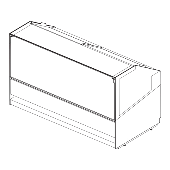
This appliance is exclusively intended to: DISPLAY AND SELL SPREADABLE GELATO DISPLAY AND SELL OF FRESH PASTRY The manufacturer is not liable for injury to persons or damage to property or the appliance itself caused by the displaying of products other than those described above. THE APPLIANCE IS INTENDED FOR PROFESSIONAL USE Uses not allowed •... - Page 12 COMPOSITION CONE HOLDER OPTIONAL SCOOP WASHER OPTIONAL ACCESS TO VALVE THERMOSTATIC CONDENSER INTERNAL CONDENSING UNIT PASSAGE PIPES IN PLATFORM OUTPUT POWER SUPPLY CABLE ACCESS TO POWER PANEL, POWER SWITCH, THERMAL PROTECTOR AND TRANSFORMERS DISPLAY + KEYBOARD 428000843137 3DSHOW USE AND MAINTENANCE MANUAL...
-
Page 13: Safety
SAFETY The appliance is equipped with safety devices. The buyer is responsible for training personnel using the appliance on the risks, safety devices and general health and safety rules required by the laws of the country where the appliance is installed. Users/operators should be aware of the position of all the controls and how they work, as well as of the features of the appliance. -
Page 14: Explosive Atmosphere
EXPLOSIVE ATMOSPHERE The equipment must not be located in an area classifi ed as an explosion risk according to 1999/92/EC such as: Zone 0 An area in which there is a permanent, long-lasting or frequently explosive atmosphere made up of a mixture of air and fl... -
Page 15: Disposal Of Waste Material
DISPOSAL OF WASTE MATERIAL During normal operation, the appliance does not generate any environmental contamination. At the end of its life cycle, or if it is necessary to proceed to permanent decommissioning, we recommend following the procedures below: DISPOSAL (USER) The symbol, applied to either the product or its packaging, indicates that the product should not be considered as normal domestic waste, but should be taken to a waste collection point for the recycling of electrical and electronic appliances. -
Page 16: Installation
INSTALLATION This manual supplies the information necessary for correct unpacking, procedures for positioning and connection to mains electricity. STORAGE AND UNPACKING The appliance, with or without the packaging, should be carefully stored inside warehouses or in areas away from the elements and direct sunlight, at a temperature between 0 and +40 °C. -
Page 17: Environmental Conditions
ENVIRONMENTAL CONDITIONS ATTENTION A dry room that can be ventilated is the suitable location for the appliance’s installation. There should be a good air fl ow around the compressor/condensing unit.Therefore the area around the unit should not be obstructed by boxes or other objects. Place the equipment away from sources of heat (radiators, heaters of any kind, etc.) and far from the infl... -
Page 18: Positioning / Levelling
POSITIONING / LEVELLING WARNING PIVOTING WHEELS WITH BRAKE (OPTIONAL) The equipment is set up with pivoting wheels with brakes for easy handling and positioning. It is absolutely necessary after placement stabilise the equipment on the fl oor. WARNING HEIGHT ADJUSTABLE FEET The equipment is set up with adjustable leveling feet in height. -
Page 19: Maintenance
MAINTENANCE The Staff in charge of the appliance must control and respect the expiry dates for maintenance, given in the table below, calling the authorised Technical After-sales assistance when indicated. OPERATION FREQUENCY PERSONNEL AUTHORISED USER CLEANING THE EXTERNAL SURFACES CLEANING THE ACCESSIBLE INTERNAL PARTS (without the use of tools) CONTROL POWER SUPPLY CABLE, PLUGS AND / OR ELECTRICAL SOCKETS... -
Page 20: Faults - Technical After-Sales Assistance
If the control unit is set up especially for must R290 refriger- ant, it must only be replaced with an original replacement from ISA. Replace the temperature probes only after checking which of the two is not operating effi ciently. -
Page 21: Alarms List (Where Present)
10.1 ALARMS LIST (WHERE PRESENT) ALARMS PERSONNEL ALARM DESCRIPTION OUTPUTS AUTHORISED Broken thermostat probe. • The alarm starts a few seconds after the probe breaks down; it TECHNICAL Compressor output ac- stops a few seconds after the probe starts working again properly. ASSISTANCE cording to “COn”... -
Page 22: Technical Specifications
TECHNICAL SPECIFICATIONS H117 H135 H117 H135 Lenght 1172 1502 1667 1832 2162 Depth 1104 External dimensions H117 1170 / 1670 Height H135 1350 / 2005 H117 Weight (net) H135 428000843137 3DSHOW USE AND MAINTENANCE MANUAL... -
Page 23: Containers Arrangement Gelato (Optional)
11.1 CONTAINERS ARRANGEMENT GELATO (OPTIONAL) VG 120 LAYOUT KIT SPACERS CONTAINERS 428000843137 3DSHOW USE AND MAINTENANCE MANUAL... - Page 24 11.1 CONTAINERS ARRANGEMENT GELATO (OPTIONAL) VG 155 LAYOUT KIT SPACERS CONTAINERS 428000843137 3DSHOW USE AND MAINTENANCE MANUAL...
- Page 25 11.1 CONTAINERS ARRANGEMENT GELATO (OPTIONAL) VG 170 LAYOUT KIT SPACERS CONTAINERS 428000843137 3DSHOW USE AND MAINTENANCE MANUAL...
- Page 26 11.1 CONTAINERS ARRANGEMENT GELATO (OPTIONAL) VG 190 LAYOUT KIT SPACERS CONTAINERS 428000843137 3DSHOW USE AND MAINTENANCE MANUAL...
- Page 27 11.1 CONTAINERS ARRANGEMENT GELATO (OPTIONAL) VG 220 LAYOUT KIT SPACERS CONTAINERS 428000843137 3DSHOW USE AND MAINTENANCE MANUAL...
-
Page 28: Technical Plant
11.2 TECHNICAL PLANT CABINET FEET 32 mm DRAIN PIPE Ø 25 mm REFRIGERANT PIPE CABLE OUTLET CONTROL BOARD WHEEL WHEEL + BRAKE CUSTOMER SIDE CROSSING PIPES 428000843137 3DSHOW USE AND MAINTENANCE MANUAL... -
Page 29: Open/ Close Front Glass
11.3 OPEN / CLOSE FRONT GLASS Open / close manually the front glass as shown in the fi gure using the special central handle. WARNING APERTURE Accompany evenly glass while opening. The front glass has a front opening limited; do not force absolutely the opening beyond the limit allowed. CLOSURE During the closing phase in last stretch the glass is pulled toward the small columns from the mechanism to ensure the correct closure. -
Page 30: Lighting
11.4 LIGHTING ON / OFF 11.5 GLASS ATTENTION Is absolutely forbidden to place weights on glass surfaces. 428000843137 3DSHOW USE AND MAINTENANCE MANUAL... -
Page 31: Max Load On Shelves Vp
11.6 MAX LOAD ON SHELVES ATTENTION The load limits indicated for each shelf must be respected to avoid their deformation or breaking. 11.7 OPENING / CLOSING SLIDING ATTENTION To open and close the exhibition space horizontally scroll slides without force and close them manually making sure of their complete closure;... -
Page 32: Control Panel
CONTROL PANEL ON / OFF switch heating glass top usable to eliminate the formation of condensation in special weather conditions. WARNING The electronic control board is installed already programmed. Any changes to the control board settings can be carried out exclusively by qualifi ed technical personnel. 428000843137 3DSHOW USE AND MAINTENANCE MANUAL... - Page 33 CONTROL PANEL START-UP Plug the appliance in at the socket supplied by the customer, ensuring that the plug is fi tted with an earth contact and that there are no multiple sockets connected to it. At the fi rst start-up and after any period of inactivity longer than 8 hours without power (with the socket unplugged - button “8”...
-
Page 34: User Interface
12.1 USER INTERFACE BUTTON PRESSURE SINGLE BUTTON In program, it pages through the codes of the parameters or increases the value. If it is pressed for 3 seconds it allows access to the section menu. Holding it pressed in for 3 seconds starts the manuale defrost cycle. If pressed during display time, it allow the defrosting scheduled to be set-up. - Page 35 12.1 USER INTERFACE BUTTON PRESSURE SINGLE BUTTON TO SEE AND MODIFY THE SET POINT Press and release the SET key (6): the set point will be displayed immediately. The SET LED fl ashes. To change the Set value push the buttons (1) and (5). To memorize the new set point, press the SET button (6) or wait 15 seconds to exit programming.
- Page 36 12.1 USER INTERFACE SIGNIFICATION ON: Solenoid valve activated BLINKING: Programming phase (blinking togheter with LED ON: Fan on BLINKING: Programming phase (blinking togheter with LED ON: Defrost activated BLINKING: Dripping time in process ON: Keyboard in “ALL” mode BLINKING: Keyboard in RVM mode (remote control) ON: Alarm signal In program “Pr2”...
- Page 37 12.1 USER INTERFACE BUTTON PRESSURE SINGLE BUTTON To view or change the set point. In programming mode it selects a parameter or confi rm an operation. If pressed for 3 seconds while the maximum or the minimum temperature reset. To see the maximum temperature reached. In programming it scrolls the parameter codes or increases the value.
- Page 38 12.1 USER INTERFACE TO SEE THE MIN TEMPERATURE • Press and release the button. • You will see the message “Lo” followed by the minimum temperature. • Press the button or wait 5 seconds to display the normal temperature. TO SEE THE MAX TEMPERATURE •...
- Page 39 12.1 USER INTERFACE LOCK / UNLOCK KEYBOARD TO LOCK THE KEYBOARD • Hold keys for a few seconds until the message “POF” fl ashing. At this point, the keyboard is locked; It permitted only to see the set point, the maximum and minimum temperature.
-
Page 40: Cleaning
CLEANING The materials listed below must be cleaned as follows: STAINLESS STEEL Only use warm water and non-aggressive detergents and then rinse and dry using a soft cloth. ACRYLIC OR POLYCARBONATE Wash with lukewarm water, using a soft cloth or a chamois cloth. Do not use abrasive cloths or sponges. -
Page 41: Condensing Unit
13.2 CONDENSING UNIT (REMOVABLE) ATTENTION Turn off the product, wait a few hours until the equipment of the condensing unit has reached a temperature close to that of the environment. Rimuovere carter e griglie posteriori svitando le relative viti di fi ssaggio (6) come indicato. Clean the condensing unit using a suction brush.Clean the condenser with a soft bristle brush;... -
Page 42: Prolonged Appliance Switch-Off
PROLONGED APPLIANCE SWITCH-OFF • Remove the product contained in the refrigerated compartment and place it immediately in a special refrigerator conservative to ensure proper storage. • Open the equipment and wait for it to reach room temperature and then clean it. •... - Page 43 ATTACHMENTS WIRING DIAGRAM - 412100802000 - 1/3 428000843137 3DSHOW USE AND MAINTENANCE MANUAL...
- Page 44 ATTACHMENTS WIRING DIAGRAM - 412100802000 - 2/3 428000843137 3DSHOW USE AND MAINTENANCE MANUAL...
- Page 45 ATTACHMENTS WIRING DIAGRAM - 412100802000 - 3/3 428000843137 3DSHOW USE AND MAINTENANCE MANUAL...
- Page 46 ATTACHMENTS WIRING DIAGRAM - 412100812000 - 1/3 428000843137 3DSHOW USE AND MAINTENANCE MANUAL...
- Page 47 ATTACHMENTS WIRING DIAGRAM - 412100812000 - 2/3 428000843137 3DSHOW USE AND MAINTENANCE MANUAL...
- Page 48 ATTACHMENTS WIRING DIAGRAM - 412100812000 - 3/3 428000843137 3DSHOW USE AND MAINTENANCE MANUAL...
- Page 49 ATTACHMENTS BASE ASSEMBLY 428000843137 3DSHOW USE AND MAINTENANCE MANUAL...
- Page 50 ATTACHMENTS DUCTING Screw M8x40 50010803309 VITE VTE M8X40 ZINC B UNI5739 Quantity Washer W9213104 RONDELLA ZN 8,4X17X1,5 MM Quantity 50021100309 DADO M8 FLANG. ZINC. B. DIN6923 Quantity Screw M6x45 50010101909 VITE VTCEI M6X45 ZINC B UNI 5931 Quantity Washer 50030003703 ROND.
- Page 51 ATTACHMENTS ACCESSIBILITY COMPONENTS CONTROL PANEL Unscrew the screws (6). Manually remove the case rear casing SX from home to make accessible the components of the control panel. 428000843137 3DSHOW USE AND MAINTENANCE MANUAL...
- Page 52 ATTACHMENTS ACCESSIBILITY COMPONENTS POWER PANEL POWER SWITCH THERMAL PROTECTOR TRANSFORMERS Unscrew the screw (1). Manually remove the case rear casing SX from home and manually remove the casing of the power panel (A). Under the housing of the power panel housing the drawer of the transformers (B) that can be extracted manually.
- Page 53 ATTACHMENTS ACCESSIBILITY COMPONENTS THERMOSTATIC VALVE Unscrew the screw (1). Manually remove the case rear casing DX from home to make accessible the Thermostatic Valve. 428000843137 3DSHOW USE AND MAINTENANCE MANUAL...
- Page 54 ATTACHMENTS ASSEMBLY INSTRUCTIONS SCOOP WASHER DRAIN PIPE 1/2” WATER PIPING 1/2” 428000843137 3DSHOW USE AND MAINTENANCE MANUAL...
- Page 56 Bastia Umbra - Perugia Italy Tel. +39 075 80171 Fax +39 075 8000900 www.isaitaly.com...
Need help?
Do you have a question about the 3DSHOW 120 and is the answer not in the manual?
Questions and answers