
Summary of Contents for IMI TA TA-FUS1ON-C
- Page 1 TA-FUS1ON-C Combined control & balancing valves With independent EQM characteristics...
-
Page 2: Key Features
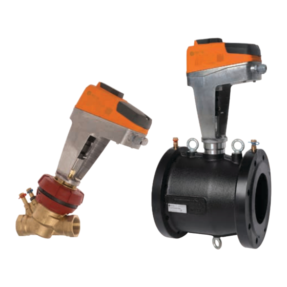
IMI TA / Control valves / TA-FUS1ON-C TA-FUS1ON-C These innovative balancing and control valves for heating and cooling systems combine the key hydronic functions of balancing and control in one valve. Adjustable Kvs and inherent independent EQM characteristics allow correct valve sizing and optimum system controllability. The measuring points enable accurate measurement of flow, differential pressure, temperature and available differential pressure. -
Page 3: Measuring Accuracy
Surface treatment: Connection: DN 32-50: Non treated DN 32-50: DN 65-150: Electrophoretic painting. Female thread according to ISO 228. Thread length according to ISO 7-1. Male thread according to ISO 228. Marking: DN 32-50: TAH, IMI, DN, PN, DR, serial No and flow direction DN 65-150: Flanges according to EN-1092-2, type 21. -
Page 4: Correction Factors
IMI TA / Control valves / TA-FUS1ON-C Correction factors The flow calculations are valid for water (+20°C). For other a flow deviation that increases with small valves, low settings liquids with approximately the same viscosity as water and low differential pressures. Correction for this deviation can (≤20 cSt = 3°E=100S.U.), it is only necessary to compensate for... - Page 5 Sizing diagram DN 65-150: Recommended setting range 7.5–10 (≈40–100% of Kvs).
-
Page 6: Selection Tables
IMI TA / Control valves / TA-FUS1ON-C Selection tables Maximum recommended pressure drop (ΔpV) for valve TA-Slider TA-Slider TA-MC100 and actuator combination 1250 FSE/FSR The maximum recommneded pressure drop over the valve and [kPa] [kPa] [kPa] actuator combination for close off (ΔpV... - Page 7 With fail safe actuators TA-MC100FSE TA-MC100FSE TA-MC100FSR TA-MC100FSR Input signal: 0(2)-10 VDC, 0(4)-20 mA, 0(2)-10 VDC, 0(4)-20 mA, 3-point 3-point 3-point 3-point Output signal: 0(2)-10 VDC, 0(4)-20 mA 0-10 VDC 0(2)-10 VDC, 0(4)-20 mA 0-10 VDC Supply voltage: 24 VAC 230 VAC 24 VAC 230 VAC...
-
Page 8: Closing Force
IMI TA / Control valves / TA-FUS1ON-C Closing force Necessary force (F) to close the valve versus the differential pressure (ΔpV ), without exceeding stated leakage rate. close Close [kPa] DN 80 65 100 32-50 TA-Slider 750 TA-Slider 1250 TA-MC100FSE/FSR... -
Page 9: Installation
Installation Application examples Installation of actuator 2-way direct circuit Approx. 140 mm of free space is required above the actuator. >140 >140 TA-FUSION-C Ingress protection IP54 Injection circuit Note: Read carefully the installation instruction of the actuator. TA-Slider 750/TA-Slider 1250 DN 32-50 TA-FUSION-C DN 65-150... - Page 10 IMI TA / Control valves / TA-FUS1ON-C Operating function DN 32-50 Setting Measuring ΔpV and q Connect IMI Hydronic Engineering balancing instrument to the measuring points. Input the valve type, size and setting and the actual flow is displayed. Measuring ΔH Connect IMI Hydronic Engineering balancing instrument to the measuring points.
- Page 11 Articles – Sets DN 32-50 Female threads Threads according to ISO 228 TA-Slider 750 Input signal: 0(2)-10 VDC, 0(4)-20 mA, 3-point, on-off >140 24 VAC/VDC Article No ØD1 PN 16 G1 1/4 12,9 5902276884603 322205-50711 G1 1/2 18,5 5902276884665 322205-50811 33,0 5902276884726 322205-50911...
- Page 12 IMI TA / Control valves / TA-FUS1ON-C DN 100-150 With flanges Flanges according to EN-1092-2, type 21. TA-Slider 750 / TA-Slider 1250 (DN 150) Input signal: 0(2)-10 VDC, 0(4)-20 mA, 3-point, on-off >140 24 VAC/VDC Article No PN 16 5902276893193...
- Page 13 Articles – Fail-safe sets, extending (closing) DN 32-50 Female threads Threads according to ISO 228 TA-MC100FSE Input signal: 0(2)-10 VDC, 0(4)-20 mA, 3-point >140 24 VAC Article No PN 16 G1 1/4 12,9 5901688820162 22106-081032 ØD1 G1 1/2 18,5 5901688820209 22106-081040 33,0 5901688820247...
- Page 14 IMI TA / Control valves / TA-FUS1ON-C Articles – Fail-safe sets, retracting (opening) DN 32-50 Female threads Threads according to ISO 228 TA-MC100FSR Input signal: 0(2)-10 VDC, 0(4)-20 mA, 3-point >140 24 VAC Article No PN 16 G1 1/4 12,9...
- Page 15 Articles – Valves Female thread ØD1 Threads according to ISO 228 Article No PN 16 G1 1/4 12,9 7318798639207 22106-001032 G1 1/2 18,5 7318798639306 22106-001040 33,0 7318798639405 22106-001050 Male thread ØD1 Threads according to ISO 228 Article No PN 16 G1 1/2 12,9 7318794015906...
- Page 16 IMI TA / Control valves / TA-FUS1ON-C Articles – Actuators TA-Slider 750, TA-Slider 1250, TA-MC100FSE/FSR (Available as sets with TA-FUSION) For more details on actuators, see separate technical leaflets or contact IMI Hydronic Engineering. Type Supply voltage Article No TA-Slider 750...
- Page 17 Accessories Measuring point Article No DN 32-50 M14x1 7318792813207 52 179-014 M14x1 7318793858108 52 179-015 DN 65-150 7318792813009 52 179-008 7318792814501 52 179-608 Extension for measuring point M14x1 Suitable when insulation is used. Article No For DN 32-50. M14x1 7318793969507 52 179-016 Measuring point Extensions 60 mm.
- Page 18 IMI TA / Control valves / TA-FUS1ON-C Connections for DN 32-50 Welding connection Swivelling nut Valve Pipe Article No Max 120°C G1 1/2 7318792748806 52 009-032 7318792748905 52 009-040 G2 1/2 7318792749001 52 009-050 Soldering connection Swivelling nut Valve Pipe Article No Max 120°C...
- Page 20 IMI TA / Control valves / TA-FUS1ON-C The products, texts, photographs, graphics and diagrams in this document may be subject to alteration by IMI Hydronic Engineering without prior notice or reasons being given. For the most up to date information about our products and specifications, please visit www.imi-hydronic.com.