Advertisement
Quick Links
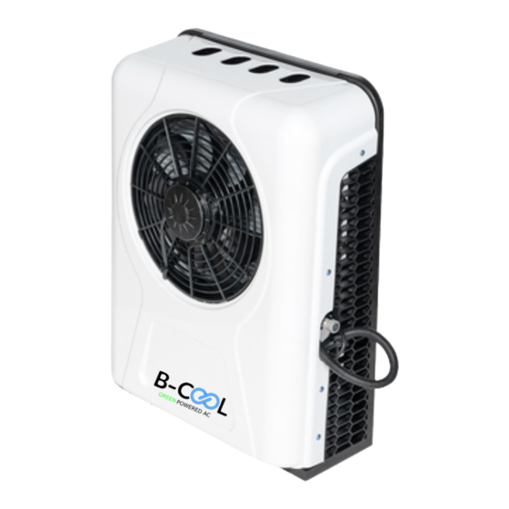
Advertisement

Related Manuals for DC Power Solutions B-COOL12000Flex5H


Summary of Contents for DC Power Solutions B-COOL12000Flex5H
- Page 1 SPLIT UNITS SPLIT UNITS Installation Manual www.dcpowersales.com...
- Page 2 SAFETY INSTRUCTION Installation must be performed by Unit is heavy. Do not handle or a professional install the unit alone. Wear goggles and gloves for the installation Switch off / disconnect battery Do not remove any protection before installation provided on the unit.
- Page 4 each box contains injection molding 3 points hose connection line Remote Controller 5 points hose Install Screws Air Conditioner Backpack high Power Harness pressure pipe (12v) Air Conditioner Power Harness Compressor Shock Pad (24v)
- Page 5 Recommended Recommended Recommended Hole Cut Sizes Hole Cut Sizes Hole Cut Sizes B-COOL12000Flex5H 50 mm x 50 mm 1.97 in x 1.97 in B-COOL12000WMB 50 mm x 50 mm 1.97 in x 1.97 in...
- Page 6 STEP 1. Remove the Outer Casing Fix the damping pad and sleeve at the marked points on the external machine.
- Page 7 STEP 2. Before Punching a Hole Mark the punch position (before making a hole) (select 5 installation points)
- Page 8 STEP 3. Punching a Hole for Installation Punch a Hole using a drill ( 8 mm drill). Use a pull riveter to fix the pull rivet nut at the marked hole.
- Page 9 STEP 4. Fixing the Damping Pads Fix the damping pad and sleeve at the marked points on the external machine.
- Page 10 STEP 5. Install the External Unit Install the External Unit...
- Page 11 STEP 6. Install the Expansion Valve Connecting the Expansion Valve...
- Page 12 STEP 7. Install the Internal Machine Mounting Plate & Evaporator Install the Internal Machine Mounting Plate. Install the Evaporator...
- Page 13 STEP 8. Connecting the Compressor Connect the 5/8 inch low pressure pipe to the compressor...
- Page 14 STEP 9. Wiring the Internal Unit Connect the internal and external machine wire and power cord...
- Page 15 STEP 10. Connecting the Evaporator Connect Internal and External Pipe to the Evaporator Install the drainage pipe...
- Page 16 STEP 11. Vacuuming the System Vacuum for 35 - 40 mins...
- Page 17 STEP 12. Refill Refrigerant Refill Refrigerant (Pure R134a) 600g...
-
Page 18: Battery Connection
STEP 13. Battery Connection Connect the power cord to the battery. - Page 19 STEP 14. Attach the Outer Casing This Finishes the Installation.
- Page 20 STEP 15. Switch on the A/C FLIP OVER FOR "OPERATING INSTRUCTIONS"...
- Page 21 SPLIT UNITS SPLIT UNITS OPERATING MANUAL www.dcpowersales.com...
- Page 22 operating instructions control panel control panel remote control...
- Page 23 operating instructions Turn on A/C: Long Press the On / Off button to operate the A/C Setting the Temperature: Press the down button to lower the temperature. Press the up button to increase the temperature. Setting the Wind Speed: Press the arrow up button to enter the windspeed settings.
- Page 24 operating instructions Setting the Cut Off Voltage: Every B-COOL branded air conditioner comes with a voltage cut off feature. Turn off the air conditioner, press the arrow up and arrow down key at the same time. This will let you enter the voltage setting.
- Page 25 troubleshooting - Air Conditioner Condition Solution(s) Select the right mode and set proper temperature and speed. If the cooling Check if there is any obstruction at the air inlet and outlet effect is not good Check if the surface of the condenser is dirty Check refrigerant level (low pressure, high pressure).
- Page 26 troubleshooting - Air Conditioner Condition Solution(s) The control Check battery for low voltage and verify that the power panel displays source is either 12V or 24V DC voltage fault Check if the low voltage protection value is too high Check if the sensor at air inlet / outlet is plugged in The control panel correctly displays sensor...
- Page 27 troubleshooting - Air Conditioner Condition Solution(s) The control Check if the fan is correctly plugged in. Connect the fan with a panel displays separate 12V or 24V DC power source. If the fan doesn’t fan fault work, replace fan. Check if it is short of refrigerant. The control Check if the high and low voltage is within the normal panel displays...
-
Page 28: Troubleshooting
troubleshooting The B-COOL Rooftop units come pre-charged. However, should a leak or an Incident occur, the following steps must be taken. Leak Testing: Refrigerant volume (check with Glass Level) If volume is low or is lower than the previous check, investigate leak by looking for traces of oil. - Page 29 troubleshooting Emptying the System: Empty the entire system while meeting local refrigerant handling standards. We recommend at least 30-45 minutes vacuum before charging. After the unit is empty, move to charging the system and charge it with the appropriate amount for freon. Charge the System: The system should be charged by a qualified A/C technician and follow the guidelines for R134a Freon.
- Page 30 error codes(i) ERROR ERROR CODE ERROR CODE CODE Verify battery power. Ensure correct connection of power Low voltage line's positive and negative poles to battery. Check for low protect voltage settings. Loose or detached plug for evaporator motor. Evaporator Motor Failure of internal control panel Open Circuit Further Information: refer to appendix Error...
- Page 31 error codes(ii) ERROR ERROR CODE ERROR CODE CODE Compressor Loose screw on compressor phase line. Failure Compressor controller malfunction. Connection issue with internal wire of Evaporator Motor evaporator motor. Short Circuit Internal control panel malfunction.
- Page 32 error codes (iii) ERROR ERROR CODE ERROR CODE CODE Check freon level. Check for dusty condenser surface affecting heat dissipation. Compressor Check for normal condensing motor Overheating speed. Outside unit's narrow space causes poor heat dissipation. Compressor controller failure. Loose/broken fan plug or line. Condenser Fan Ejected plug pin resulting in poor Open Circuit...
- Page 33 error codes (iv) ERROR CODE ERROR CODE ERROR CODE Check for any short circuit in the condenser fan. Condenser Fan Further Information: refer to appendix Short Circuit Error Codes (vi) Failure of the compressor controller. The plug for the fan is either loose or 1#(Red plug fan) / the line is broken.
- Page 34 error codes (v) ERROR CODE ERROR CODE ERROR CODE Loose temperature sensor plug. Temperature Ejected temperature sensor plug Sensor Fault pins (poor connection).
- Page 35 error codes (vi) Inspection method of E02 Disconnect the evaporator plug from the internal control panel and connect it to a 12V/24V power source. If the evaporator motor operates correctly, it indicates that the motor is functioning properly, but the internal control panel needs to be replaced.
-
Page 36: Maintenance
maintenance Before beginning cleaning, make sure the air conditioner is turned off. Surface Cleaning of inside unit: Wipe with a clean damp cloth. The cloth can be dipped in a mild cleaning solution if the unit is very dirty. Evaporator Core: Clean with compressed air, if necessary. - Page 37 maintenance If you operate the AC in a dusty/dirty environment, Cleaning should be done more frequently. Check AC for excess dirt and dust Check evaporator Check Condenser Core Check Condenser Fan Check Drainage Plugs for clogs Apply common sense...
- Page 38 maintenance Conduct regular maintenance. Start the unit at least once every two months. Check for blockage on the top and bottom of the condenser fan; the condenser coil and air flow before and after the evaporator blower...
-
Page 39: Technical Support
technical support Should any problem occur during the operation of an air conditioner; Please review the operating manual and/or contact our Tech Repair Center. +1 778 590 5000 tech-help@dcpowersales.com www.dcpowersales.com... - Page 40 VISIT OUR WEBSITE FOR MORE INFO www.dcpowersales.com DC P ower SOLUTIONS 12V DC & 24V DC Flex Mount Split Units Manufacturer / Distributor of the B-COOL Brand of products.
Need help?
Do you have a question about the B-COOL12000Flex5H and is the answer not in the manual?
Questions and answers